A while back there was some (slight) interest expressed in posting repair projects. The Rapco GPS conditioned oscillator repair which I described a few weeks ago seemed useful to a couple of people so I though I'd post details of another project.
In this case the item is arguably more interesting than the repair - a Marconi 2024 9kHz - 2.4GHz signal generator. This is basically the same signal generator as Dave's teardown in
EEVBlog #261 but it has twice the frequency range. I picked it up on fleabay in need of a little TLC - the seller said it had "a weak display". This was his picture.
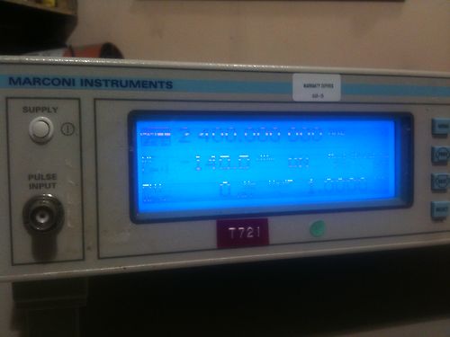
It looked like poor connections on the zebra strip in the LCD, an easy fix (I thought!) so I bought it.
Ok, got it home and powered it up. The original description was certainly correct - the display was not happy. However it worked well enough for me to do a quick check of the generator and all seemed fine apart from the LCD which was good news. The generator was fitted with options 04 (OCXO) and 11 (pulse modulation and high +25dBm output).
After a while the display seemed to improve but it was still a bit difficult to read.
From here down click on the picture for a large version.
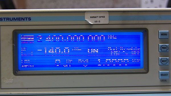
OK - time to crack it open

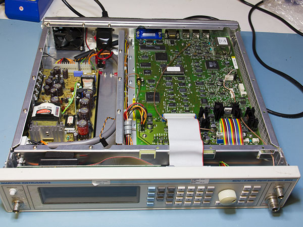
The first problem is that someone has been here first and not put the unit back together correctly - if you watch Dave's video there should be an aluminium plate screening the PSU. Ho Hum, at least they left the screws for me. Time to have a look for any more damage.
Hmmm, broken mains switch....
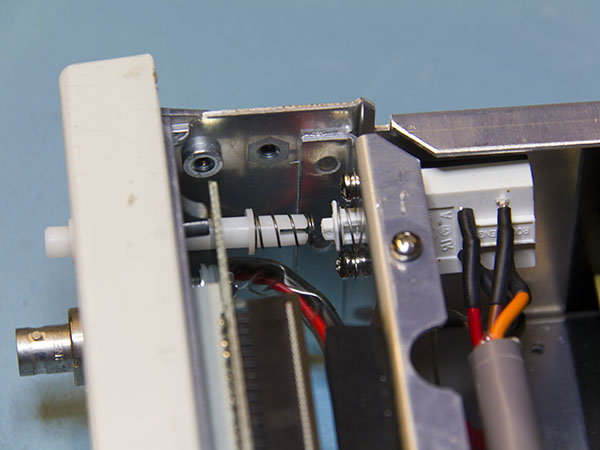
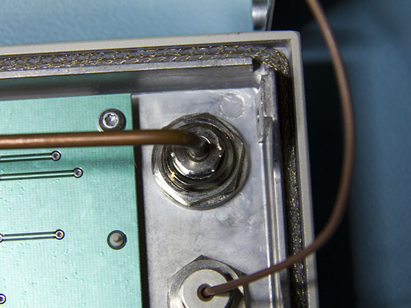
... and someone's "had a go" at the back of the N connector.....
... and there are only three screws holding the display in....
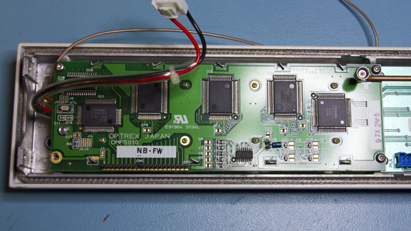
...but otherwise it doesn't look too bad.
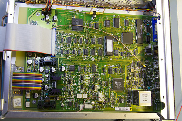
The main board is almost exactly as in Dave's teardown except for the OCXO in place of the TCXO in his 2023. Option 11 swaps out the attenuator unit for one with a higher power RF amplifier but that's hidden in the RF section. I'm not planning on opening that unless there's a clear need.
A closer look at the OCXO, it's an NDK unit but I can't find a datasheet anywhere for it.
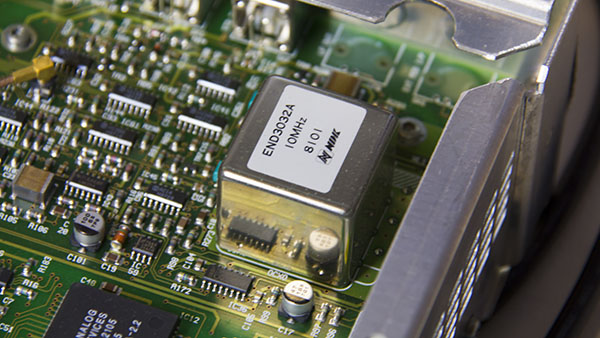
Looking at the date stamps on the various ICs and the stored calibration date it would appear to have been built in Feb 1998.
Moving on, to the LCD and I wasn't
quite as happy as I had been. The problem seems to be the row drive connections as whole rows are not displayed or are not displaying correctly but, although there's a zebra strip (the grey block in the bottom right half of the display) it's only for the column connections. There's no zebra block for the row connectors but these use a flexible PCB strip.
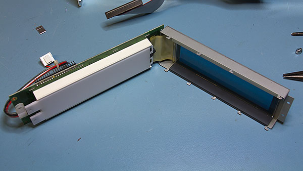
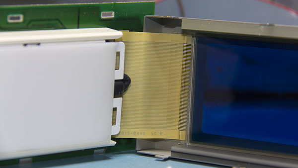
Here's a close-up of the connector. It's bonded to the PCB and to the LCD itself but it's clear that whatever I do is not going to
improve the connections. I did try a bit of pressure against the PCB end up and down the actual contacts but it didn't make any difference.
At this point I was a bit hacked off with myself for buying the sig gen - I've looked for replacement LCDs without much luck for previous items, so I was a bit doubtful whether I could locate one for the Marconi. All too often equipment has a custom panel, however this looked generic - an Optrex DMF 5010 so I ploughed on into Google.
On the positive side I found
a data sheet fairly easily. On the less good side there are few hits from suppliers - not even hits from the "we'll quote you anything" brokers. The only place I found with stock had a MOQ of 60 (which appeared to be the entire stock) - I might have considered it at the right price but £25 each before shipping and VAT
wasn't the right price

Even ebay couldn't help

More Googling and things brightened up a bit. The Optrex board has a T6963 controller so I figured if I could find a panel with the same resolution/display area and controller it might work - in the end I found one quite close to home at
Rapid Online and not all that expensive.
It's not an exact match though, it has an LED backlight, not CCFL and it's smaller at 180mm rather than 200 and about 8mm less deep, but it has a compatible controller (the RA6963) and the same pin out so I though it was worth buying one.
The first problem was to get it connected - the Winstar panel has a 2x10 pin connector, the Optrex one a 1x20. I didn't want to alter the original ribbon cable - generally if non-original parts need to be fitted I try to make things as "reversible" as possible so the plan was to use a piece of single row PCB header strip with ribbon cable soldered to make a plug to fit the cable IDC socket.
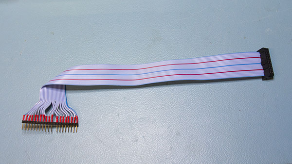
This didn't
quite work as well as I'd hoped - the strip isn't really designed to have a cable soldered to it and even keeping soldering time to a minimum and the iron temperature as low as practical the pins almost immediately became loose. You can see in the photo that they're uneven. Fortunately it worked well enough without having to come up with another solution.
Next was the LED backlight supply. This turns out to be very easy as the CCFL inverter board is powered from 5V. The Winstar data sheet says that the LED has a V
F of 3.5V and a forward current of 80mA, so with a 1.5V drop a 18ohm resistor should do nicely.
Connected it up and....
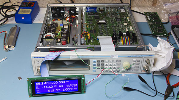
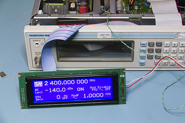
Bingo


It works!!
The next thing was to fix it in securely. I found some tiny aluminium plates, about 10x15mm in the junk box - absolutely no idea whether they had a purpose in life or were offcuts from something else but they were perfect to make small brackets to carry the new display. Two holes drilled 8.5mm apart to make up the horizontal difference and a 6mm threaded spacer to offset the panel a bit - here's what the result looks like.
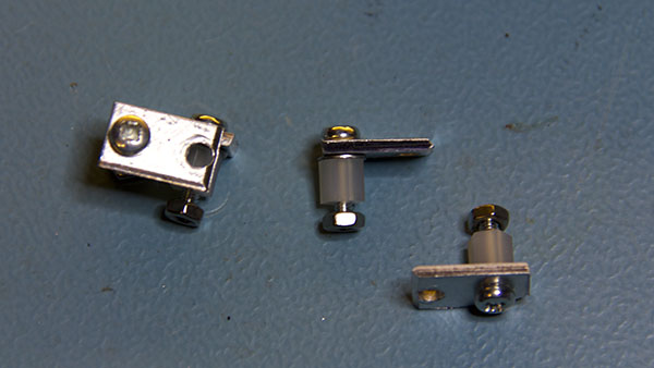
and here they are attached to the display ready to go into the front panel
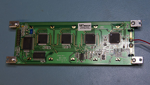
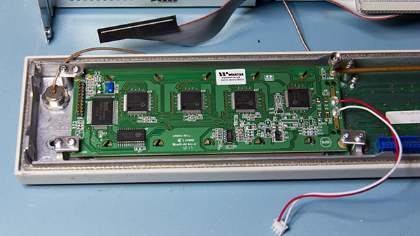
Finally here is the display mounted in the front panel and a shot of the new display in place.
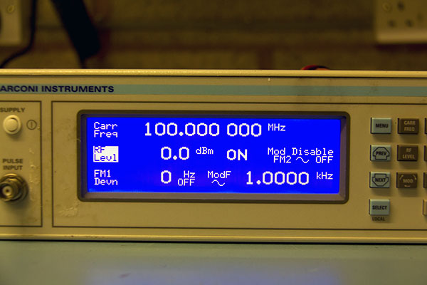
The CCFL inverter board also carries the supply for the fan, decoupled with two 470uF electrolytics and two 1mH inductors so I still need to make up a small board to reproduce that and carry the current limiting resistor for the backlight LED. I also need to fix the mains switch but have some in the spares box so that's not a problem. All in all I'm very happy with the result and it's another piece of rescued test equipment.
It's slightly disappointing that it's already impossible to find components for an item that's not even 15 years old. Looking at some of the pictures in ebay auctions for 2023's and 2024's I note that quite a few have missing display lines, so this might be a common problem. It's nice to know that a newer LCD module can be adapted fairly easily to fit.
One other piece of good news regarding the 2023/2024 is that the service manual has just been uploaded to
KO4BB's Manuals Repository. It's still in "Recent Uploads" but should be available for download fairly soon.