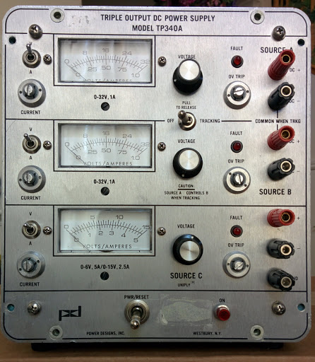
A little while ago I acquired a Power Designs TP340A listed in classic fashion as for parts or not working. Following is a little repair diary on it.

When the supply arrived, it looked fine on the outside with all appropriate controls and even its original feet. A quick look inside revealed nothing catastrophic, so I checked the main fuse in preparation to turn it on. Blown. Had to get some new ones.
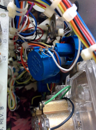
Meanwhile, the 10-turn pot (blue housing in the photo, below) for setting the voltage on Source A (the top-most channel) was popped open. Weird. I tried reassembling it a few times, but it wasn't reliable. On the low end, the wiper would pop out of alignment. Ordered a new one.

Once the I got the fuses and popped one in, it was time to see if it'd fire up. It did. With a sizzle and then the fuse blew.

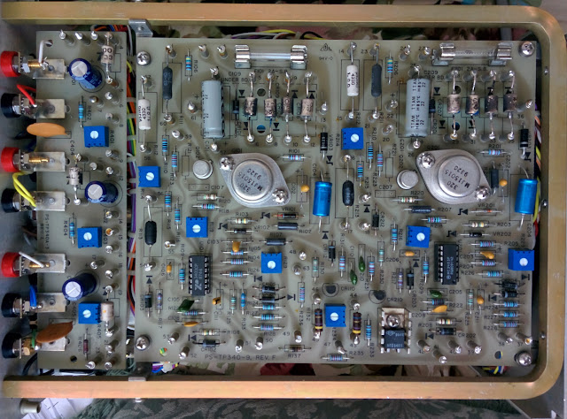
Probing around, it seemed that Source A and Source B were fine. No shorts. Diodes and transistors were behaving fine. Below is a shot of the output board (left) and Source A & B board (right). Both sources have their own fast-blow fuses and they were intact.

Continuing onto Source C (board shown below). It also has its own fuse, still intact.

Checking before the fuse there seemed to be a short at the input filter caps. You can see these whoppers on the underside of the Source C board, below.

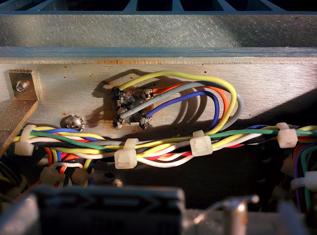
After getting some new caps to replace these, I ran into what seemed to be the bridge rectifier for Source C, based on the schematic. It's bolted to the rear of the chassis and, as you can see below, was burned to a crisp. Obviously, this is the source of the problem. The filter caps are probably fine, but since I got new ones, changed them anyway.

The schematic shows that the bridge rectifier is a BR-252. Discontinued.
http://www.mouser.com/ds/2/345/br2505-2510-11168.pdfFortunately, there are replacements by both Rectron and Fairchild. Although Mouser had the old BR-252, I opted for the newer MP-252.
http://www.mouser.com/ds/2/345/mp2505-2510-14498.pdfWhen the MP-252 arrived, I was surprised how big it was. The fried part was approximately 10mm wide, whereas the new part is 30mm wide. So, I cut open the old module and what did I find? It wasn't even the correct part. Someone made their own bridge rectifier with four puny diodes and covered it in silicone caulk!

Well, is it any wonder it didn't survive?
Installed the new bridge rectifier and probed around to verify that everything was soldered back correctly. Looked good. The moment of truth. Since I don't have a variac, it was going to be an all-or-nothing test.
Plug it in. Turn it on. Et voilà! No magic smoke.

Voltage and current settings on Source B and Source C work as expected and the analog meters match my bench meter.
So, up next is replacing the 10-turn pot for Source A and probably adjusting the trim pots. Also, I'm not a fan of the black plastic knobs that PD put on the voltage pots. They're a bit small, not aesthetically pleasing, and they leave a chasm between the front plate and the knob's flange so the shaft of the pot is visible.

The earlier TP325 with its aluminum knobs looked much better.
Stay tuned...
Jump to part 2:
https://www.eevblog.com/forum/repair/power-designs-tp340a-repair-and-facelift/msg770494/#msg770494