The Setup
With the Tenma Function Generator attached to the scope by coax... Scope on x1... Tenma in any wave-type mode... Wave amplitude at any setting... And with the wave found on the scope...
The Problem
Pulling out the offset knob to initiate offset... Turning the knob, up or down... The wave form moves to the new offset location and, then, immediately drifts back to its original location… I'm guessing a cap is failing to ground…
Schematics are attached, but I’m not certain that they are for my exact model... Any difference is in the power supply section, IIRC. Metex was a re-brand of the same units.
Review of Schematics
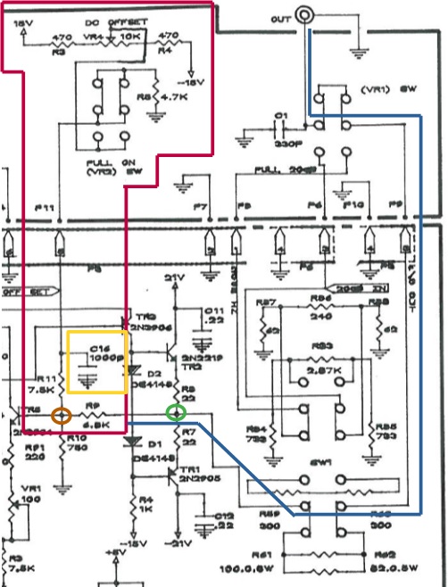
The DC offset is simply the addition of a DC voltage, meaning there is nothing fancy about the voltage itself. More in a moment. This voltage is developed in the red outlined zone and is added to the waveform at the green circle junction. The final signal then follows the blue line course to the output connector.
Creating the Offset Voltage
Both the positive voltage offset and the negative voltage offset are created via a single voltage divider network... That is, the source voltages of +15v and -15v (More about the Source Voltages, below) are supplied to a single pot, VR4, and the voltages are reduced, thereby, to the +10v and -10v offset limits. Once reduced, this voltage passes by a 1000pF decoupling capacitor, C14, and joins the waveform path at the tan circle.
Suspected Problem
As postulated previously, my guess was/is an errant cap. The review of the schematic reinforces my supposition. I propose that capacitor C14 has failed in the closed position. As reflected by the momentary jump to the new offset voltage, the divider circuit is intact, but the voltage is negated as the cap goes to ground. There is little else to fail.
The Voltage Divider
To make the divider, the positive supply is attached to the negative supply directly across the pot through series resistors. Another postulation would be that the pot had failed. But, to create the errant behavior, the wiper would have to make contact for a moment and then fail. This seems unlikely to me; I would think the wiper was making contact, or not.
More on the Supply Voltage
See schematics. The Offset Supply Voltage is developed using typical means of a transformer, having multiple secondaries leading to full bridge rectification and regulation via LM7xxx series v regs. Additional decoupling capacitors are provided on the main board.
In writing this description of the voltage supply, it comes to mind that
- the decoupling caps could create the same symptoms and
- that the electrolytic caps are more suspect than the ceramic C14 lollipop, especially if they went to ground. Now, I am thinking that I should first investigate the C6 and C8 E-caps.
So, why am I posting? Because I am just learning and the super-duper gurus, here, may have a better idea of what to look for, given the symptoms.
I very much look forward to your suggestions and I greatly appreciate your help.


PS I am aware that the schematics are blurry, but I was lucky to find them at all. They are all I have.


