Hello fellow hobbyists.
I have an interesting thing for you today.
My only oscilloscope is equipped with integrated mutlimeter, unfortunately it's not working properly.
Previous owner claimed it worked fine before but broke down by sitting in a closet.
It's a russian oscilloscope from 1992.Parts and construction is all USSR made so it's tough to analyse it.
5MHz single channel,X input available, external trigger.
A basic scope meant for "in the field" operation.
I have a full schematic(found in internet) + entire documenation provided with the scope (shows waveforms for various points in the circuit and provides some diagrams).
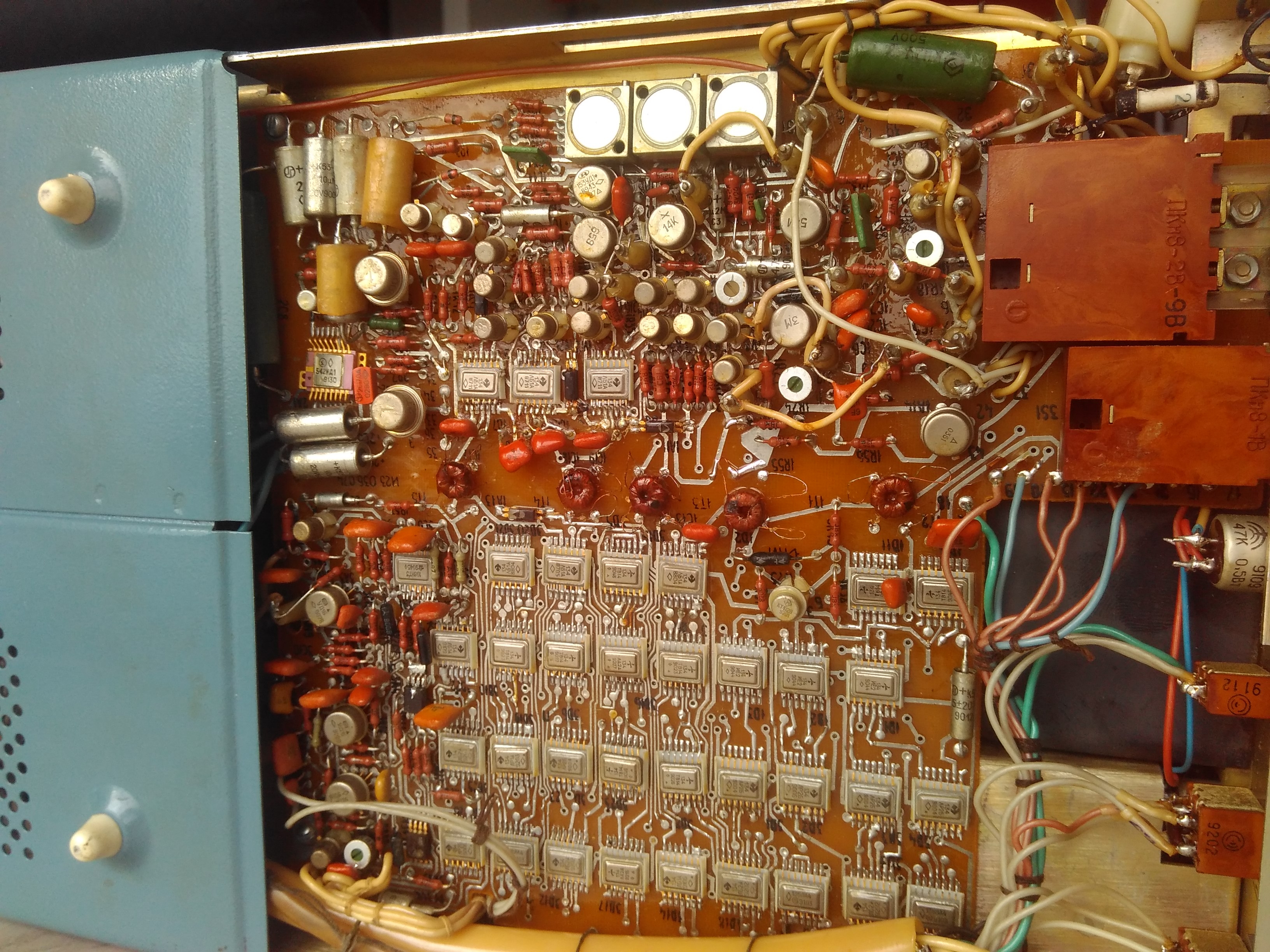
This is how the multimeter board looks like. ADC,character generator etc. is all made from discrete components/logic gates.
USSR had integrated ADCs but in this case a different approach was used.
Symptoms are as following:
-constant DC (battery) gives correct readout, pulsed DC (output of full wave rectifier)-wrong readout unless there's small load attatched across input terminals (such as analog mutlimeter)
-resistance measurement-works
-AC-wrong readouts(few % off compared to 1.5 class analog multimeter), maybe it can be corrected with onboard potentiometers as it won't show 0V even with terminals shorted,
-current measurement-value is correct but it's impossible to distinguish 0.8A from 80mA as only the dot moves, normally the numbers would shift places(it works this way on voltmeter), choosing 200mA range still gives readout with 0.8A current flow,minimum current range is 0.2mA so it should change,haven't checked pulsed DC current(would have to prepare some test circuit),will have to do some further checks here.
Tried working on it by checking for shorts/broken components.Transformers(isolation, they pass TTL signals in original way) seem to be fine as touching their terminals on either side has effect on readout.
+5V rail powering TTL parts is fine (USSR TTL parts are not very sensitive to it anyway).
I guess it's the analog circuitry that is borked.
Bloc schematic, it uses written russian so letters are different ("m" for example is "t", in printed russian T=T M=M, cannot get used to that

).

I'm not sure what to look for with such symptoms.
I'm studying automatics so ADC converters were only vaguely explained.
Fixing this multimeter would give me some more working equipment. Currenty operating on 1970 analog ERA UM3a meter (1 class for DC,1.5 class for AC) + some cheapo 5USD digital meter.
Unless I finally decide to purchase the cheap AN8008/8009

.
I'm polish so I can "decode" russian to some extent as long as I transliterate from cyrillic to latin (polish alphabet is just bit modified latin alphabet) because it's both slavic languages.
As far as I know there are some exotic USSR TTL chips on this board. If I understood the documentation correctly there's a 2xNAND/2xNOR chip.
Not quite sure as USSR naming scheme and western equivalent tables vary a bit.
Added full schematics as attachment.
If you take a close look at the board then you will notice that even resistors have their own marks(such as 1R55) which makes finding certain parts easier, logic schematic part is a mess.
Looking into chip documentation is neccessary as only pins are provided on schematic.
If needed I can make more photos or even short video clips.


