Hey everyone!
After staring at this broken oscilloscope in a cardboard box gathering dust for the past 4-5 months, I finally figured it all out. It's been the thing keeping me up at night.
Nope. I still haven't gotten anywhere with it unfortunately. But here goes another shot at it again.
Sorry about the late update, I haven't actually worked on it or attempted to repair it again until now.
I've looked it over again and here's some notes:
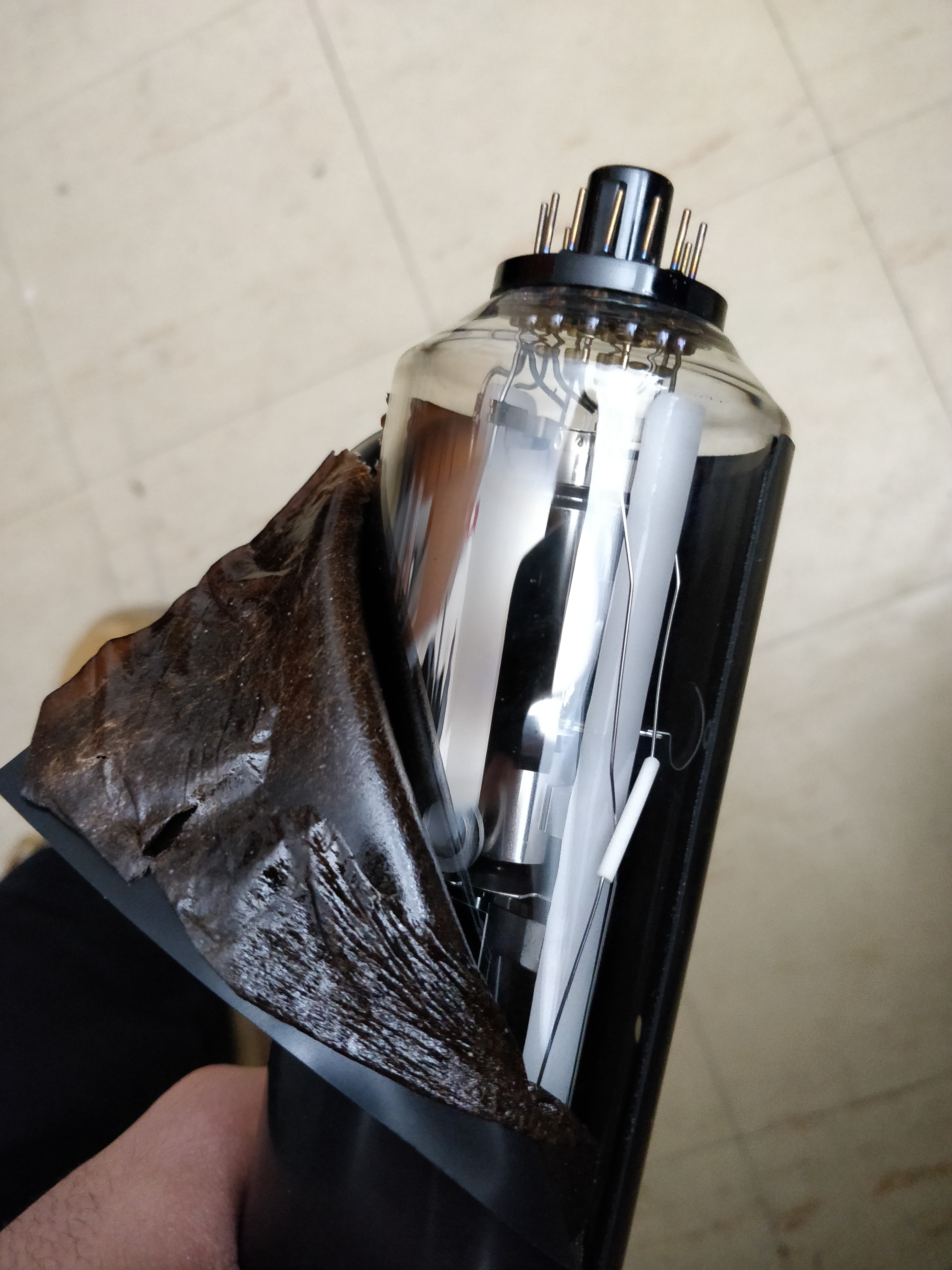
(Click my images to see bigger pictures)I removed some of the insulation wrap off the CRT neck to properly inspect it:

Getter flash looks good.
Shiny chrome/silver, no white at all. Inside components look good. No idea what this black insulation is, but I just quietly wrapped it back on.
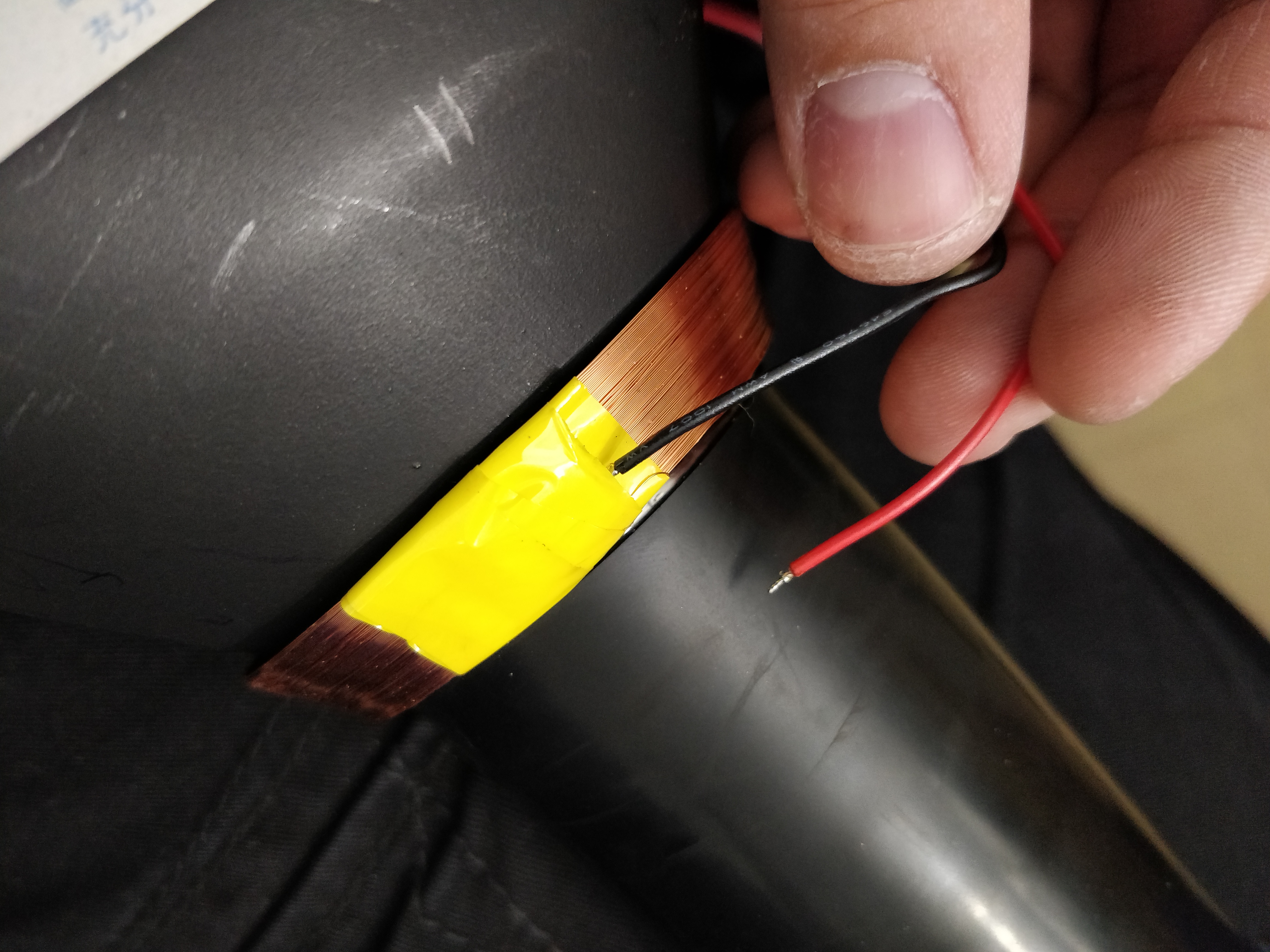
Then this happened to the yoke coil
(Or maybe it was like this already and I didn't catch it.)
Fantastic.
I re-soldered the red wire back onto the small copper coil wire that was disconnected beneath the yellow insulation tape, but I had to slightly cut through the tape in order to get the wire out. Not sure what kind of tape this actually is. Trying to find some replacement tape.
I pushed the wires back under different layers of the tape (as they were before) so they don't make contact to anything else, or each other. Hopefully this doesn't disturb the deflection of the CRT.
After looking for cracks on the PCB's as some members have suggested, I found that after gently bending the high voltage/power supply PCB (PEF-999B in my case) that something was "creaking". One of the ground leads of the voltage multiplier (MUT1001) was loose. I re-soldered it, and it sits firmly again. I'm not entirely sure if this could have been a source of my problems, but hey why not? I'll keep checking for damaged traces/loose components.
Before I turned it back on to check the voltage rail points, I found something interesting:
The schematic for the HV board show a small PCB mount 400mA(?) fuse, F1001, on the +55V line that I didn't notice before.
(Page 85 on the owner's manual. Thanks Chris56000!) After checking it's continuity, it seems to be flat out dead.
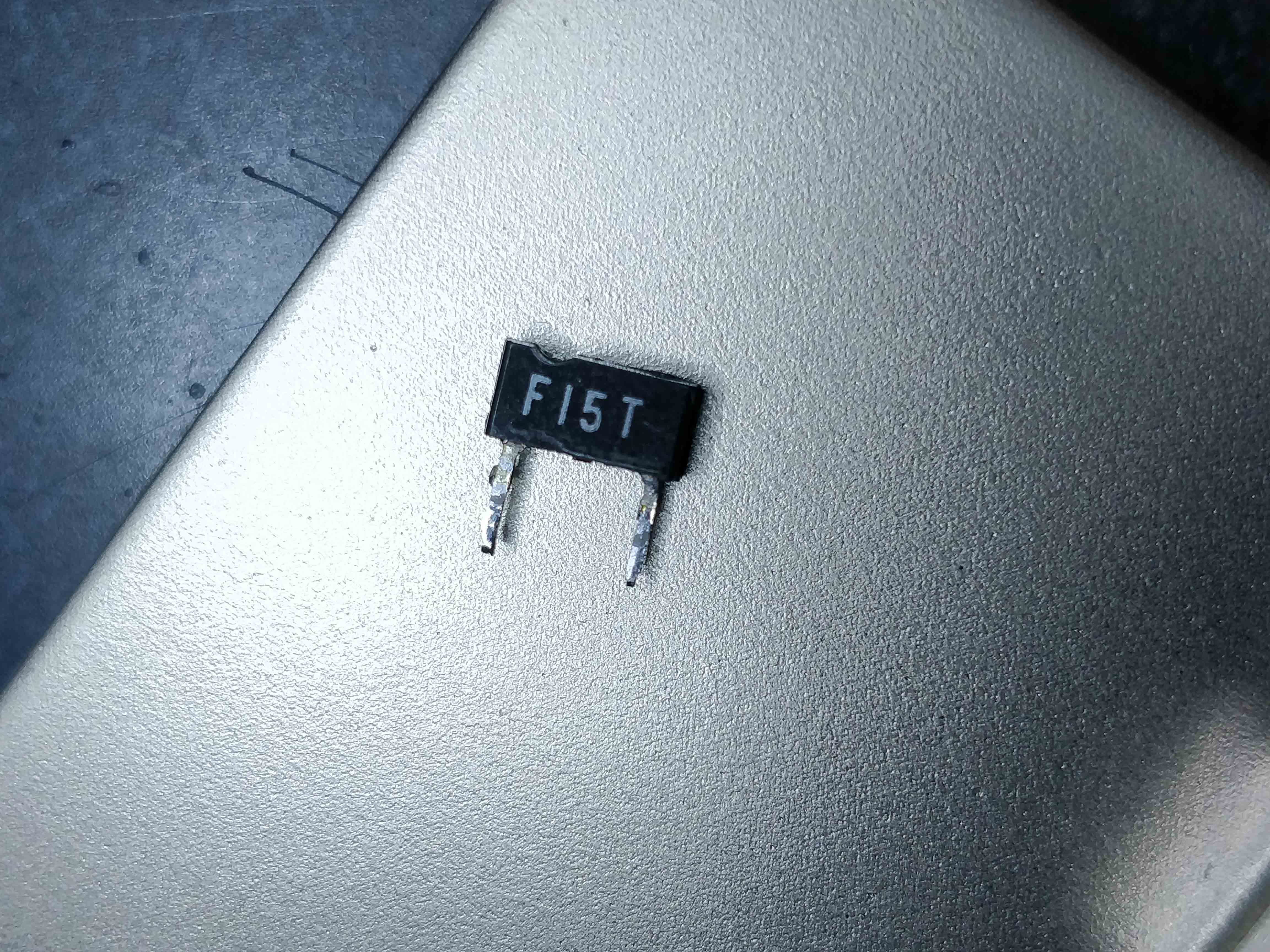
Thing is, it's not an ordinary fuse but is a "Integrated circuit protector"
(...So it's a fuse?)
A bit of a bizarre fuse package I've never seen before.
From what I've found so far, it's an ICP-F15 from ROHM Co. The schematics show a wrong "ICP-
F18" for some reason, and it's datasheet shows it as a
600mA fuse, not 400mA.
The datasheet is
here. What's bizarre is that this fuse is rated for 50V but regardless was placed on the 55V line? Not sure if 5V makes such a difference on a fuse.
I found replacement fuses on some sites I've never heard of. I'll try them out anyway.
But i'm worried that not too many of these fuses still exist, and if there's more problems on the board, the fuses might blow again when I attempt to test it.
Wondering what kind of an effect might occur if I temporarily run a cheaper, more easily available 500-600mA fuse with a higher internal resistance for testing?
ICP-F15's seem to only have an internal resistance of 0.135 Ohms. Neat?
Anyways, I have good hopes that the CRT tube itself should still be intact, and it leaves me to focus on searching for other problems on the PCBs. I might do something I keep seeing on this forum and recap the boards as well. Wouldn't hurt. I'll keep this updated when I can about my progress and whatever I find, for those interested. Any advice anyone shares is still always welcome!
Edit: I just realized I actually haven't worked on it/replied to this thread for more than just "4-5 months". Woosh. How did time fly by so fast!? My bad if i'm necroing this thread. Wow.