That is correct. However, the energy loss is not due to any resistance what so ever.
Hello there,
But what you are suggesting is not real because there is ALWAYS some resistance no matter how small, and considering that i had qualified my previous statement about not having any other losses.
We must first allow other losses to exist before we can think otherwise. For example, if we allow radiation then we can say that it becomes an antenna.
I do agree and understand what you and others are saying.
What really got me interested in to this problem was the 50% energy loss was independent of the resistor. So, if the 50% energy is lost no matter size resistor we put there, maybe there is something else behind this phenomenon.
The circuit analysis operate on voltages and currents, and we need to model this energy transfer problem in circuit analysis domain. Of course, using the circuit analysis, you will get absurdly high current etc. but the analysis will produce expected answer ie. it seems that 50% of energy is lost into resistor independently of the resistor value.
Ok, I went into physics 101 dealing with capacitors. The capacitance, charge and the voltage are related as follows:
Eq 1:

It is also said that work is needed to move charge from one capacitor plate to another, which will result higher electrical potential between the plates.
Eq 2:
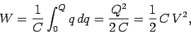
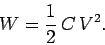
The energy stored in the capacitor is the same as the work required to charge the capacitor:
Eq3:
Now, lets take two identical 100uF capacitors C1 and C2. The C1 and C2 has following initial terminal voltages:
V1 = 3V
V2 = 0V.
Thus, we can calculate the initial charge of those two capacitors Q=V*C:
Q1 = 300uC
Q2 = 0C.
We can also calculate the energies stored in those capacitors W=Q*V/2:
W1 = 450uJ
W2 = 0J.
Total charge in the system is Q = Q1 + Q2 = 300uC. Total system energy is W = W1 + W2 = 450uJ.
Now, let's start moving some charge from the C1 to C2 until the capacitors contain equal electrical potential ie. V1 = V2. In this case, the resulting voltage will be 1.5V:
V1 = 1.5V
V2 = 1.5V
The resulting charges will be equal as the both capacitors are 100uF:
Q1 = 150uC
Q2 = 150uC
Thus, the resulting energies will also be equal:
W1 = 112.5uJ
W2 = 112.5uJ
And the total energy in the system is W1 + W2 = 225uJ.
Yes, 50% of the system's energy has been lost while moving some charge from one capacitor to another. And look, no resistors here.
Of course, one might argue that in practice wires are required to move the charge from C1 to C2, and the wires will definitely contain resistance, thus the missing energy must have been lost in this resistance. This has also been confirmed with the circuit analysis and circuit simulator in this thread. However, we needed to introduce this [artificial] resistance in order to be able to apply the kirchhoff's equations for the circuit analysis, yet we only wanted to move some charge from one capacitor to another.
Hello again,
I think i understand what you are looking for here, but one thing we have to make clear first. That is, theory is a measuring tool which which we can use to measuring real life systems. Some things in theory can not be done in the real world, because they would violate basic physical principles. The best we can do sometimes is create an experiment that gets close to what we are looking for. In addition to that, we have to first make sure we are using the right theory.
For the example of two caps, we can not assume zero resistance because not only will that not be possible, there will also be some inductance in series. Also, if the resistance was low enough, even a superconductor would not hold up because superconductors have limits just like regular conductors although they may be different.
If we had two capacitors of any physical size, there has to be some resistance, but if we let that resistance be small, then we are going to see some decent radiation as well. If we let that resistance approach zero then we would see an increase in radiation. The radiation would have to be an impulse, at least in theory. But again, i dont think there is any way to get zero resistance because there is nothing that can conduct with zero resistance when the current is infinitely high.
Also, because we live in a physical space, there is some distance between the caps, so there would be some inductance, and that inductance would act as a delay in the rise of the current wavefront. That would mean that we might see the effects we see with an inductor that was placed in the circuit on purpose, which could mean a more effective transfer of energy.
So rather than model it as a resistor and capacitor and ask the question about zero resistance, i think we have to model it as an inductor with the resistor and capacitor, because there will be some inductance there too. If we let the distance approach zero, then the two capacitors would have to become one and the same capacitor, with twice the plate areas, where the charge still has to move from one plate area to the other. Thus, the very act of moving them together would change the total energy in the system. We'd have to get down to the theory of how they would be moved together to figure out how the energy changed. They may move together under the force of the charges, or they may move apart, but i think they would actually rotate into a minimum energy position. When the charge starts to move however, energy would radiate, so we'd loose energy as they moved closer to each other.
But you can start to see, and i think you already understood this, that when we ask questions that are more complicated we have to resort to a more physical model. We can not use models that are based on simpler assumptions intended to quickly answer simpler questions to answer much more complex questions. We have to choose a model that fits the question. We try to use the simplest model that will be possible for that particular problem. But we have to make sure we use a model that includes all the effects we want to look at. For a super simple example, we dont have to use a resistor with a small cap in parallel to answer a simple question about how a resistor voltage divider works, even though there is always some small capacitance present, but when we get into higher frequency circuits we can not leave out the small parallel capacitance or we will never know how the circuit really works.


