That is correct. However, the energy loss is not due to any resistance what so ever.
Hello there,
But what you are suggesting is not real because there is ALWAYS some resistance no matter how small, and considering that i had qualified my previous statement about not having any other losses.
We must first allow other losses to exist before we can think otherwise. For example, if we allow radiation then we can say that it becomes an antenna.
I do agree and understand what you and others are saying.
What really got me interested in to this problem was the 50% energy loss was independent of the resistor. So, if the 50% energy is lost no matter size resistor we put there, maybe there is something else behind this phenomenon.
The circuit analysis operate on voltages and currents, and we need to model this energy transfer problem in circuit analysis domain. Of course, using the circuit analysis, you will get absurdly high current etc. but the analysis will produce expected answer ie. it seems that 50% of energy is lost into resistor independently of the resistor value.
Ok, I went into physics 101 dealing with capacitors. The capacitance, charge and the voltage are related as follows:
Eq 1:

It is also said that work is needed to move charge from one capacitor plate to another, which will result higher electrical potential between the plates.
Eq 2:
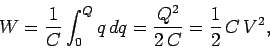
The energy stored in the capacitor is the same as the work required to charge the capacitor:
Eq3:
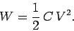
Now, lets take two identical 100uF capacitors C1 and C2. The C1 and C2 has following initial terminal voltages:
V1 = 3V
V2 = 0V.
Thus, we can calculate the initial charge of those two capacitors Q=V*C:
Q1 = 300uC
Q2 = 0C.
We can also calculate the energies stored in those capacitors W=Q*V/2:
W1 = 450uJ
W2 = 0J.
Total charge in the system is Q = Q1 + Q2 = 300uC. Total system energy is W = W1 + W2 = 450uJ.
Now, let's start moving some charge from the C1 to C2 until the capacitors contain equal electrical potential ie. V1 = V2. In this case, the resulting voltage will be 1.5V:
V1 = 1.5V
V2 = 1.5V
The resulting charges will be equal as the both capacitors are 100uF:
Q1 = 150uC
Q2 = 150uC
Thus, the resulting energies will also be equal:
W1 = 112.5uJ
W2 = 112.5uJ
And the total energy in the system is W1 + W2 = 225uJ.
Yes, 50% of the system's energy has been lost while moving some charge from one capacitor to another. And look, no resistors here.
Of course, one might argue that in practice wires are required to move the charge from C1 to C2, and the wires will definitely contain resistance, thus the missing energy must have been lost in this resistance. This has also been confirmed with the circuit analysis and circuit simulator in this thread. However, we needed to introduce this [artificial] resistance in order to be able to apply the kirchhoff's equations for the circuit analysis, yet we only wanted to move some charge from one capacitor to another.


