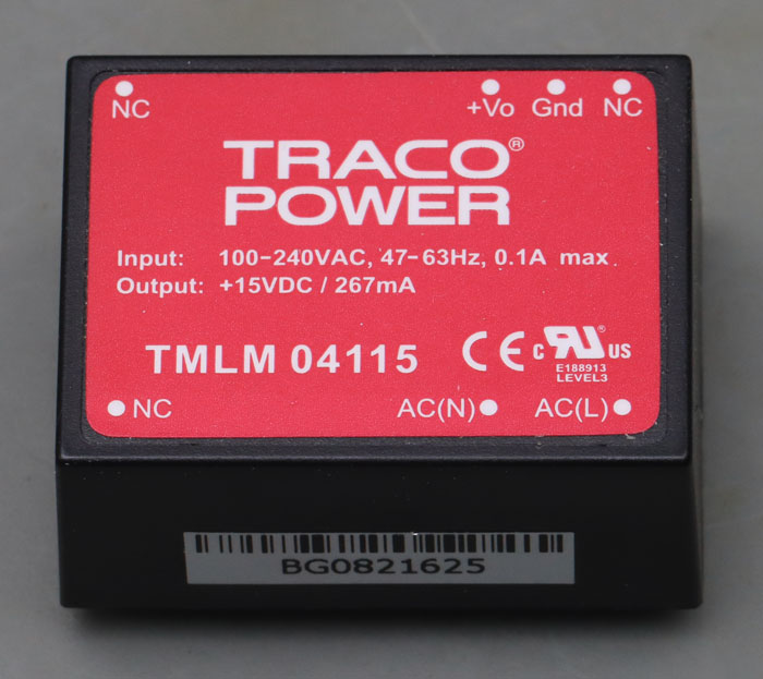
Traco Power manufactures various AC/DC and DC/DC converters, which are generally known for good quality. The TMLM series has a wide range input (90-246VAC) and offers output powers between 4W and 20W. The TMLM04115 generates 15V with a power handling capacity of 267mA. Efficiency is rated at 74%. Dimensions are 36,5mm x 27mm x 17,1mm.
The model here is a relatively early failure. It has blown a upstream 1A fuse.
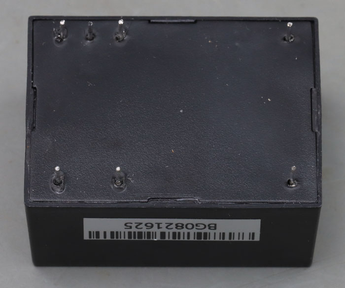
The case has seven pins, two of which only serve to stabilize the module. The switching regulator is located in a plastic cup that has been potted and closed with a lid on the bottom.
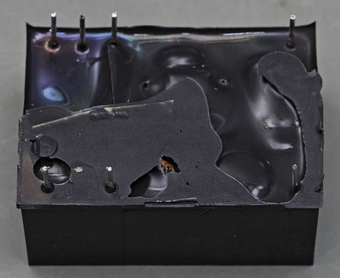
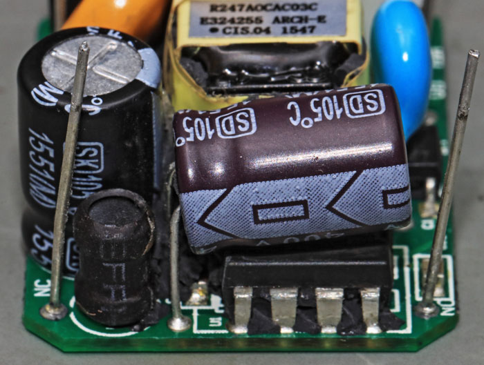
The silicone-like potting can be removed easily. The high packing density of the components is immediately noticeable.
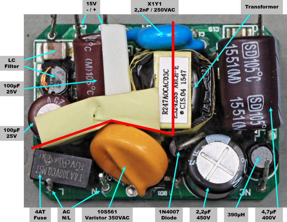
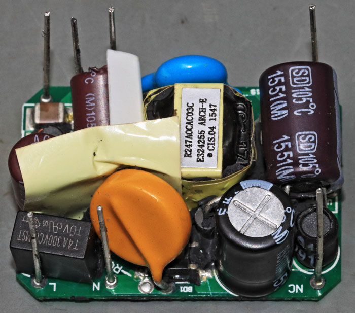
The galvanic isolation between the mains voltage and the output voltage is clearly visible. In the lower and right area are the circuit parts that work with mains voltage. In the upper left corner the low voltage part is built up. The isolation section is bridged in the middle by a transformer and a blue Y1 capacitor.
Since the input and output circuits are directly next to each other at the left edge, an additional foil had to be inserted here for isolation. To the left of the transformer, a plastic element has been inserted, whose function is not quite clear. The transformer itself seems to be sufficiently insulated. Maybe the plastic element guarantees a minimum distance to the Y1 capacitor.
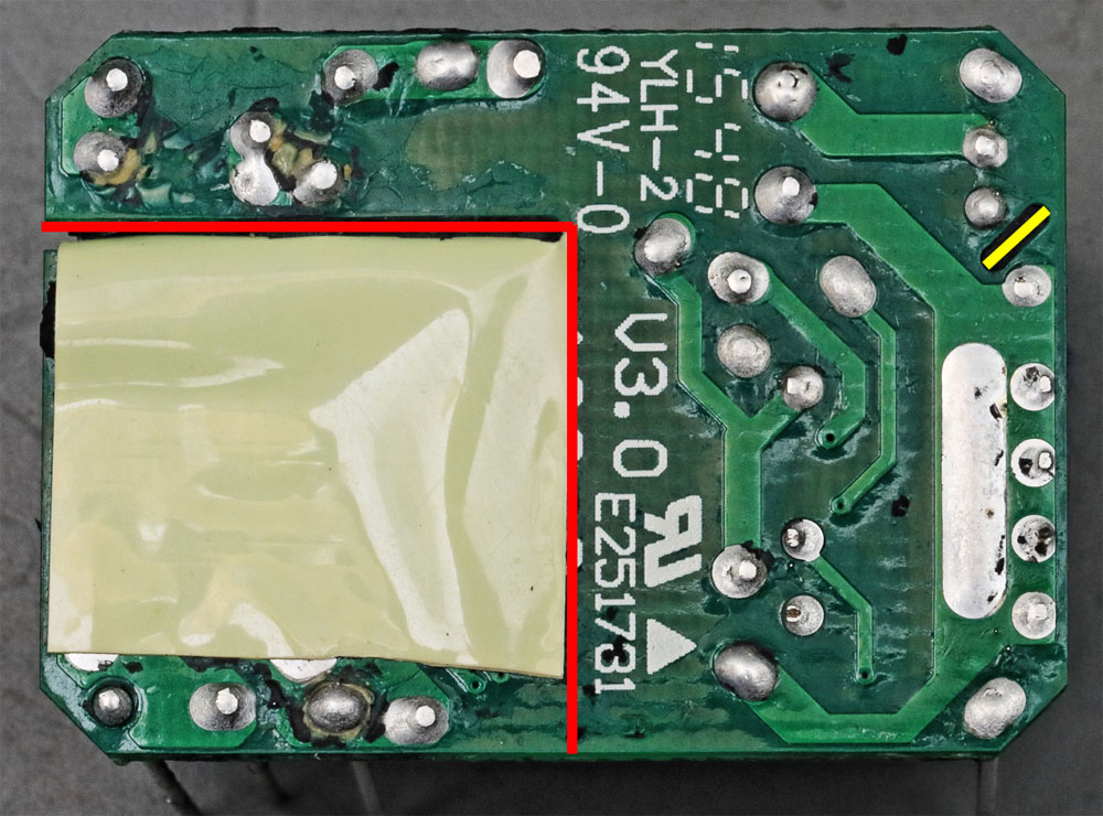
On the bottom side of the board, the foil for isolating the mains voltage has been glued to the low voltage area. At the right edge the potentials of the mains voltage are so close to each other that a slot had to be milled into the board.
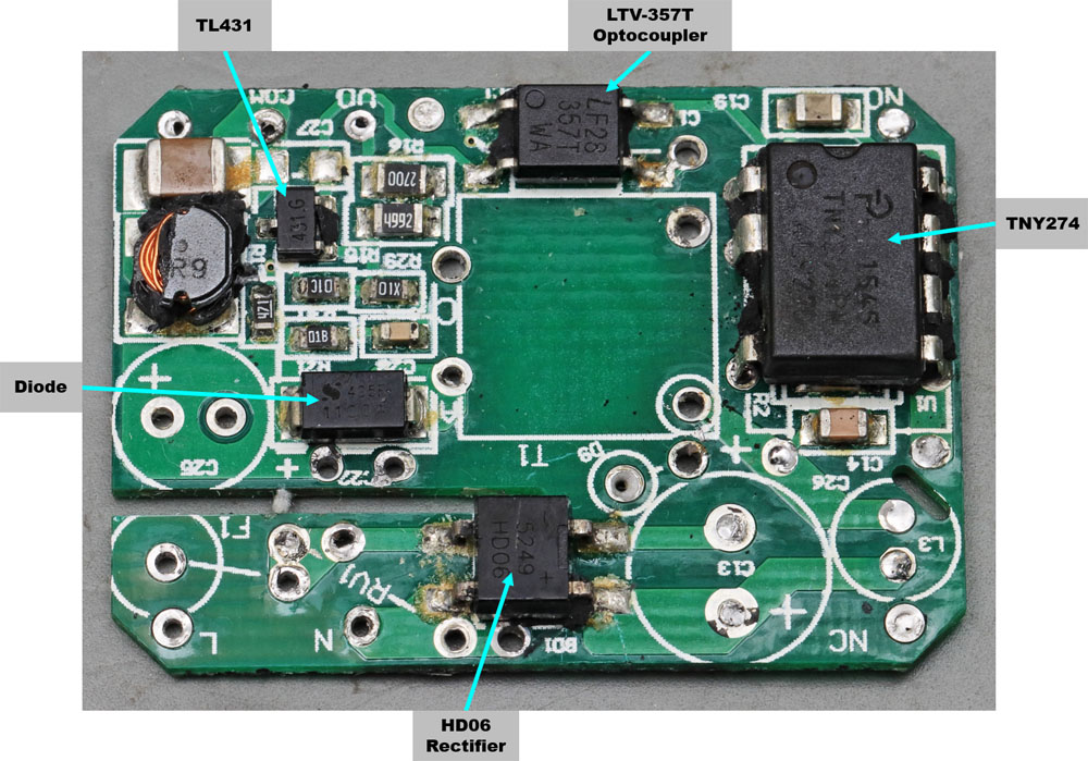
If you remove the large elements, the lower components become visible. The damage to the inductor in the upper left corner was done while removing the potting.
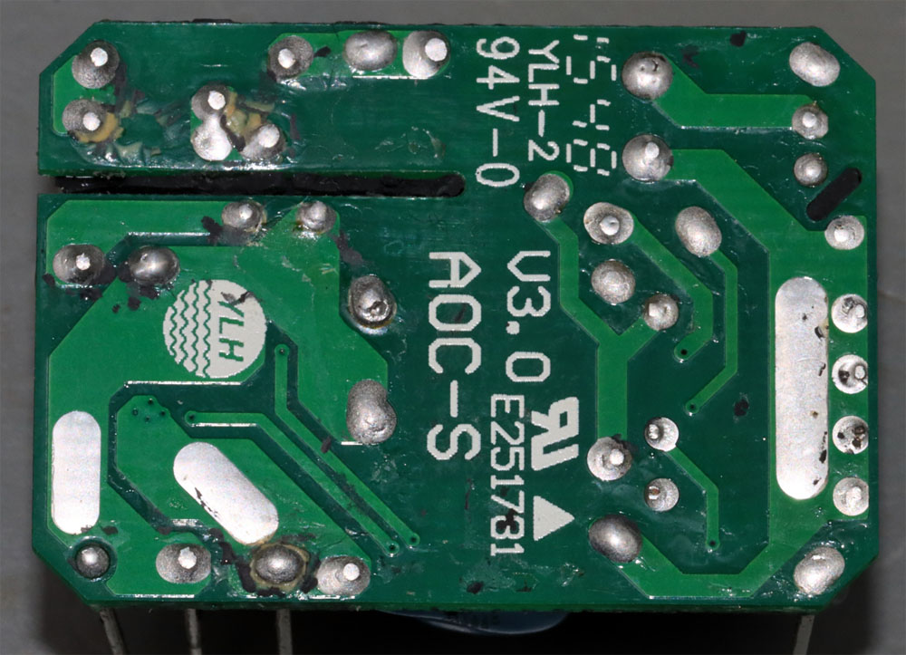
Underneath the insulation foil, it shows that the PCB was manufactured by the Chinese manufacturer YLH Electronics.
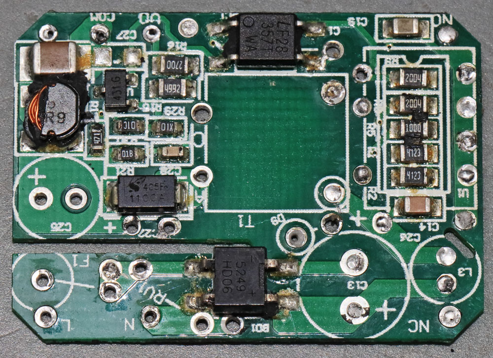
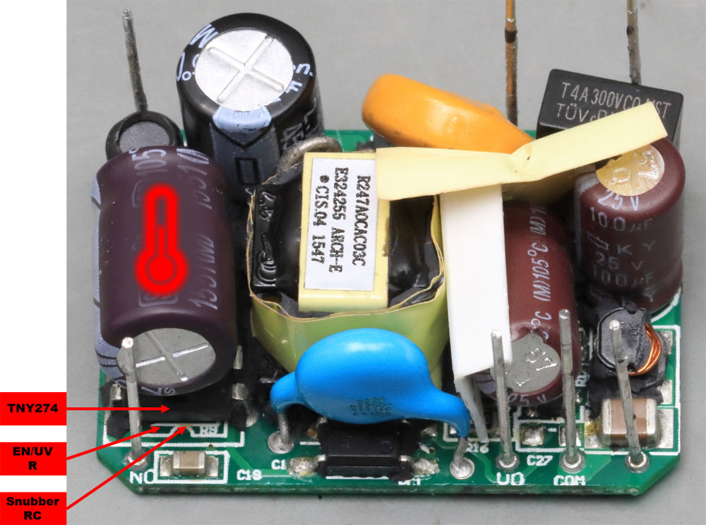
The last components only become visible when the TNY274 is desoldered. Five resistors are soldered under this component.
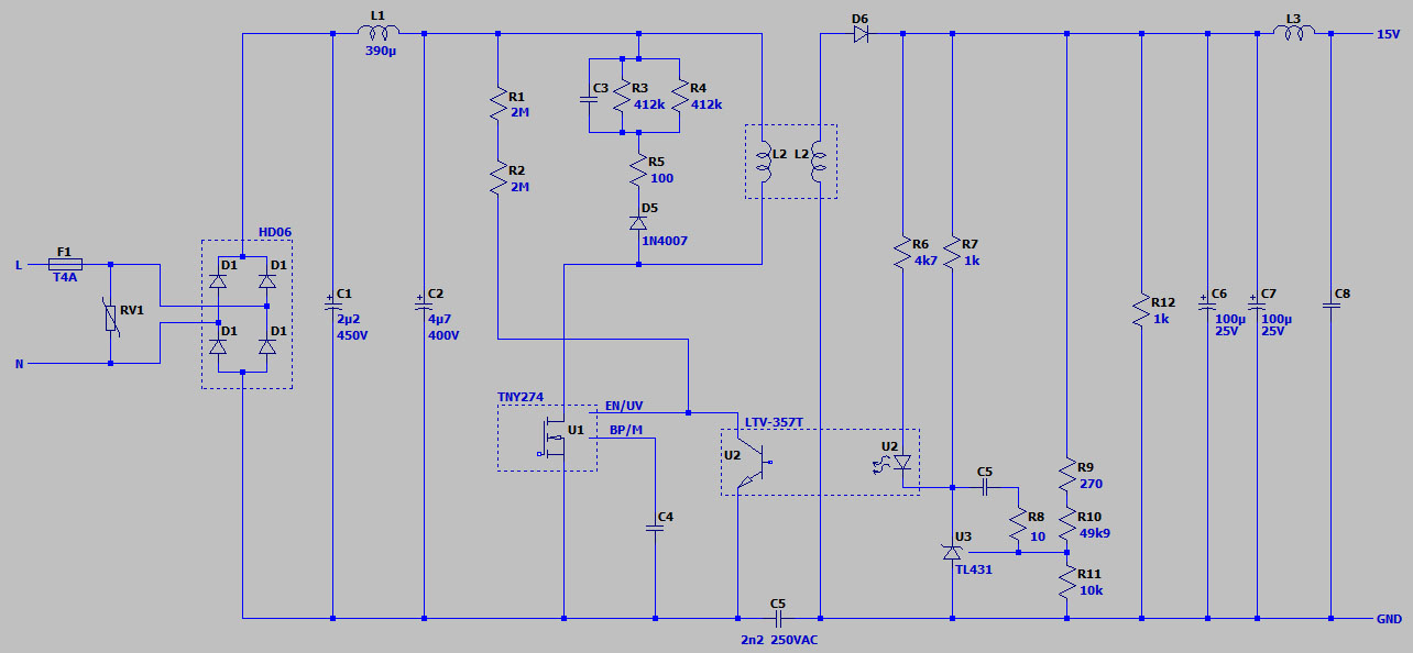
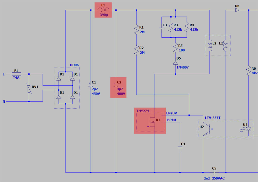
The circuit is not too complex. It is a typical flyback converter. Although the datasheet calls for a 3,15A slow-blow fuse externally, there is an additional 4A slow-blow fuse at the input. This is followed by a 350VAC varistor to protect against overvoltage pulses. The HD06 bridge rectifier safely blocks up to 600V.
On the primary side, two electrolytic capacitors are found, separated by a 390µH inductor. C1 is mainly used for smoothing the rectified line voltage. C2, as an intermediate circuit capacitor, supplies the current peaks that the switching regulator absorbs. The inductance L1 ensures on the one hand that the capacitor C1 is not loaded with the fast current changes and reduces on the other hand the emission of noise into the supply network.
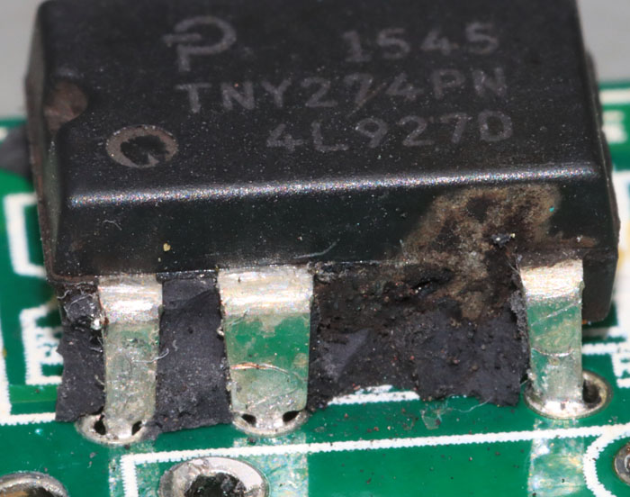
The TNY274 is a switching regulator that contains not only the controller but also the power transistor. It is from Power Integrations' TinySwitch-III family. Its clock frequency is 132kkHz. According to the datasheet, it can provide up to 5W of output power in a sealed package. Parallel to the primary coil of the transformer is the snubber circuit C3/R3/R4/R5/D5, which reduces the voltage peaks when the power transistor is switched off.
The transformer has just two windings. The TNY274 supplies itself directly from the power circuit, more precisely from its drain pin. An internal voltage regulator charges capacitor C4. While the power transistor is active, it serves as energy storage.
On the secondary side, rectification is done via D6. The capacitors C6/C7 absorb the energy packets and thus ensure a smoothed output voltage. The LC filter L3/C8 reduces the emission of high-frequency noise. Resistor R12 provides a minimum load so that the module operates stably even in no-load operation.
The output voltage is compared with the reference voltage of a TL431 shunt regulator. The voltage divider R9/R10/R11 defines the reference voltage. The RC element R8/C5 optimizes the behavior of the circuit at high frequencies. The magnitude of the output voltage defines the current through the LTV-357T optocoupler, which is the feedback of the switching regulator. Through the resistors R1/R2 the switching regulator monitors the mains voltage so that it can switch off in case of undervoltage.
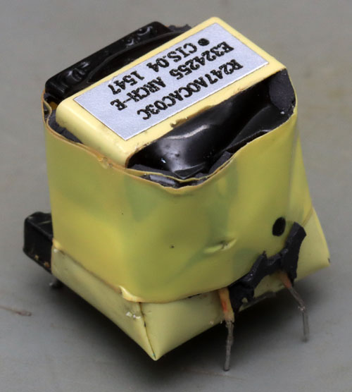
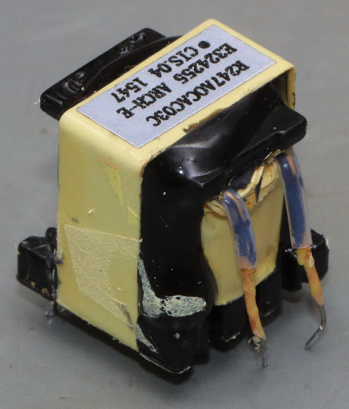
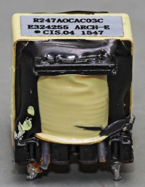
The transformer itself is potted with a hard black compound. The thicker leads of the secondary side were guided through the plastic body and fix the transformer to the PCB. The thin wires of the primary side run through the transformer body to the PCB without any guide. The wires from the primary and secondary sides are additionally insulated with tubing. The distance and the additional insulation are necessary to be able to represent the reinforced insulation against the mains voltage.
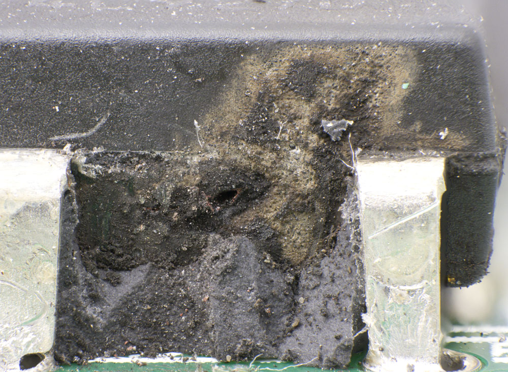
A closer look reveals that the switching regulator is definitely destroyed. A hole has burned into the side of the case and the surface of the case shows traces of a plasma.
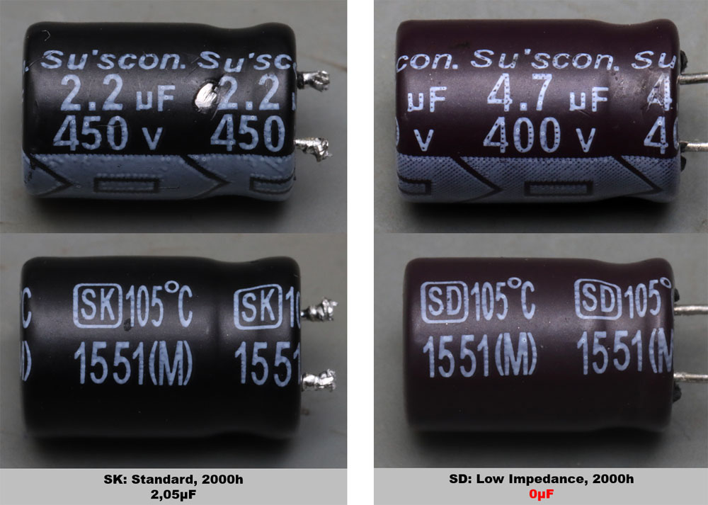
Two different electrolytic capacitors from the Taiwanese company Su'scon are used on the primary side. The less heavily loaded capacitor, which is mainly responsible for smoothing the rectified mains voltage, is one of the standard SK series capacitors. Directly on the switching regulator is an SD type with a reduced internal resistance. The lifetime of both types is specified at 2000 hours (at maximum current and temperature load). On the output side, on the other hand, there are KY capacitors from Nippon Chemi-Con with a estimated lifetime of 5000h.
It turns out that the capacitor on the switching regulator no longer offers any capacity at all.
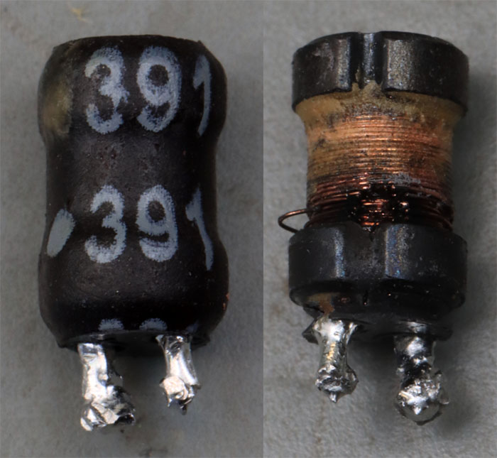
The inductance between the two electrolytic capacitors is defective too. This becomes clear when you remove the heat shrink tubing.
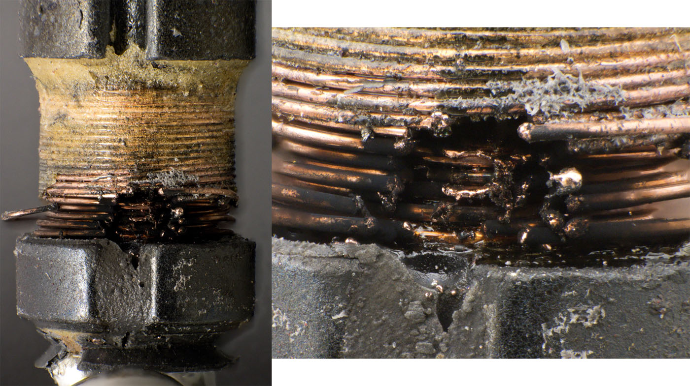
Where normally the wire of the inductor is led to the pin on the bottom side, a massive damage shows up. Several turns have melted open.
The damage of the inductance L1 could be caused by the defect of the switching regulator U1. However, this does not explain the missing capacitance of capacitor C2. It seems most likely that this capacitor was the starting point of the damage. Without sufficient capacitance at the input of the switching regulator, its supply voltage fluctuates very strongly. The inductance L1 can then even generate overvoltages. It was probably this instability that caused the switching regulator to be overloaded and eventually destroyed. The short circuit in the switching regulator then led to an overload of the inductance L1. It is quite possible that this was already overloaded before, because without the capacitor C2 much stronger current fluctuations had to be supplied from the capacitor C1. However, the inductance L1 did not interrupt the current flow like a fuse. This is shown by the many melted windings. In the end, the external fuse tripped.
If you look at the setup, it's not surprising that capacitor C2 finally led to the defect of the module. It is located directly above the switching regulator, which according to the datasheet can reach temperatures of up to 110°C at its pins. In addition to the power dissipation of the switching regulator, there is also the power dissipation of the components underneath the module (voltage measurement and snubber). The maximum permissible operating temperature of the capacitor, on the other hand, appears to be very low at 105°C, since it is also subject to a certain amount of self-heating due to its current load. The relatively short specified lifetime of 2000 hours in combination with the high load then ensures early failures.
The TNY274 datasheet specifies a rated power of 5W when used in a sealed enclosure. Traco Power specifies the TMLM family at only 4W. The reason for this is probably the limited and encapsulated installation space, which makes heat dissipation more difficult. The maximum operating temperature of the TMLM modules, which is only 60°C, also shows how critical this point is.
https://www.richis-lab.de/TMLM04115.htm 
...you are right, there is no die picture...


