Disclaimer, the following circuit has blinking lights:
Do not try any of these if prone to epileptic seizures and alike.
Whatever you'll do, will be on your own responsibility entirely.
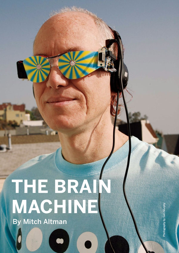
Many, many, many moons ago, did once a funny kind of LED blinker called "Brain Machine"!

The project by Mitch Altman was all the rage back then, and it really works, makes one see colors other than the LEDs' color, and other complex visual patterns. The circuit also produces a stereo sound (apart from the DOs dedicated to blink the two LEDs), but the sound doesn't seem to have any strange effect, while the blinking lights certainly have for everybody I've tested. At some point it was published in the "Make:" magazine, too.
Googled a little and, what a nice surprise, "The Brain Machine" page is still there, on the Makezine website:
 https://makezine.com/projects/the-brain-machine/
My implementation was with a different MCU, an ATtiny25, because that's what it happened to have at hand, but I've kept the same timings and waveforms for both the blinks and the audio. Found the code that I've used with the ATiny25. IIRC, I've started from a code published on Adafruit, and adapted that for my setup:
/*
 * BM1.c
 *
 * Created: 2012.04.06 07:14:21
 *
 */
/*
#include <avr/io.h>

int main(void)
{
    while(1)
    {
        //TODO:: Please write your application code
    }
}
*/
/*
Brain Machine
Firmware
for use with ATtiny25
25-Oct-07
*/


#include <avr/io.h>             // this contains all the IO port definitions
#include <avr/interrupt.h>      // definitions for interrupts
#include <avr/sleep.h>          // definitions for power-down modes
#include <avr/pgmspace.h>       // definitions or keeping constants in program memory


/*
The hardware for this project is very simple:Disclaimer:
[hr]
Do not try any of that if prone to epileptic seizures and alike.
Beware that everything you do is entirely your responsibility.
     ATtiny25 has 8 pins:
       pin 1   no connection
       pin 2   PB3 - Left eye LED1 -- through a 47 ohm resistor
       pin 3   no connection
       pin 4   ground
       pin 5   OC0A - Left ear speaker (base-frequency) -- through an LPF of 2.2K and 1uF bipolar
       pin 6   OC1A - Right ear speaker (Offset Frequencies for binaural beats) -- through an LPF of 2.2K and 1uF bipolar
       pin 7   PB2 - Right eye LED2 -- through a 47 ohm resistor
       pin 8   +3v (CR2032 through a switch)
    All other pins are unused

    This firmware requires that the clock frequency of the ATtiny
      is the default that it is shipped with:  8.0MHz internal oscillator
*/


/*
The C compiler creates code that will transfer all constants into RAM when the microcontroller
resets.  Since this firmware has a table (brainwaveTab) that is too large to transfer into RAM,
the C compiler needs to be told to keep it in program memory space.  This is accomplished by
the macro PROGMEM (this is used, below, in the definition for the brainwaveTab).  Since the
C compiler assumes that constants are in RAM, rather than in program memory, when accessing
the brainwaveTab, we need to use the pgm_read_byte() and pgm_read_dword() macros, and we need
to use the brainwveTab as an address, i.e., precede it with "&".  For example, to access
brainwaveTab[3].bwType, which is a byte, this is how to do it:
     pgm_read_byte( &brainwaveTab[3].bwType );
And to access brainwaveTab[3].bwDuration, which is a double-word, this is how to do it:
     pgm_read_dword( &brainwaveTab[3].bwDuration );
*/


// table of values for meditation
//   start with lots of Beta (awake / conscious)
//   add Alpha (dreamy / trancy to connect with subconscious Theta that'll be coming up)
//   reduce Beta (less conscious)
//   start adding Theta (more subconscious)
//   pulse in some Delta (creativity)
//   and then reverse the above to come up refreshed
struct brainwaveElement {
  char bwType;  // 'a' for Alpha, 'b' for Beta, 't' for Theta, or 'd' for Delta ('0' signifies last entry in table
  unsigned long int bwDuration;  // Duration of this Brainwave Type (divide by 10,000 to get seconds)
} const brainwaveTab[] PROGMEM = {
  { 'b', 600000 },
  { 'a', 100000 },
  { 'b', 200000 },
  { 'a', 150000 },
  { 'b', 150000 },
  { 'a', 200000 },
  { 'b', 100000 },
  { 'a', 300000 },
  { 'b',  50000 },
  { 'a', 600000 },
  { 't', 100000 },
  { 'a', 300000 },
  { 't', 200000 },
  { 'a', 300000 },
  { 't', 300000 },
  { 'a', 150000 },
  { 't', 600000 },
  { 'a', 150000 },
  { 'b',  10000 },
  { 'a', 150000 },
  { 't', 600000 },
  { 'd',  10000 },
  { 't', 100000 },
  { 'd',  10000 },
  { 't', 100000 },
  { 'd',  10000 },
  { 't', 300000 },
  { 'a', 150000 },
  { 'b',  10000 },
  { 'a', 150000 },
  { 't', 300000 },
  { 'a', 150000 },
  { 'b',  10000 },
  { 'a', 200000 },
  { 'b',  50000 },
  { 'a', 200000 },
  { 'b', 150000 },
  { 'a', 150000 },
  { 'b', 200000 },
  { 'a', 100000 },
  { 'b', 250000 },
  { 'a',  50000 },
  { 'b', 600000 },
  { '0',      0 }
};


// This function delays the specified number of 1/10 milliseconds
void delay_one_tenth_ms(unsigned long int ms) {
  unsigned long int timer;
  const unsigned long int DelayCount=87;  // this value was determined by trial and error

  while (ms != 0) {
    // Toggling PB5 is done here to force the compiler to do this loop, rather than optimize it away
    for (timer=0; timer <= DelayCount; timer++) {PINB |= 0b0100000;};
    ms--;
  }
}


// This function blinks the LEDs (connected to PB3, PB2 - for Left eye, Right eye, respectively)
//   at the rate determined by onTime and offTime
//   and keeps them blinking for the Duration specified (Duration given in 1/10 millisecs)
// This function also acts as a delay for the Duration specified
void blink_LEDs( unsigned long int duration, unsigned long int onTime, unsigned long int offTime) {
  for (int i=0; i<(duration/(onTime+offTime)); i++) {
    PORTB |= 0b00001100;          // turn on LEDs at PB3, PB2
    delay_one_tenth_ms(onTime);   //   for onTime
    PORTB &= 0b11110011;          // turn off LEDs at PB3, PB2
    delay_one_tenth_ms(offTime);  //   for offTime
  }
}


// This function starts the Offset Frequency audio in the Right ear through output OC1A  (using Timer 1)
//   to create a binaural beat (between Left and Right ears) for a Brainwave Element
//   (the base-frequency of 200.321Hz is already assumed to be playing in the Left ear before calling this function)
//   and blinks the LEDs at the same frequency for the Brainwave Element
//   and keeps it going for the Duration specified for the Brainwave Element
// The timing for the Right ear is done with 8-bit Timer 1 (set up for CTC Mode, toggling output on each compare)
//   Output frequency = Fclk / (2 * Prescale * (1 + OCR1C) ) = 8,000,000 / (2 * (1 + OCR1C) )
void do_brainwave_element(int index) {
    char brainChr = pgm_read_byte(&brainwaveTab[index].bwType);
    if (brainChr == 'b') {
      // Beta
      // start Timer1 with the correct Offset Frequency for a binaural beat for the Brainwave Type
      //   to Right ear speaker through output OC1A (PB1, pin 6)
      OCR1C = 71;  // T1 generates 217.014Hz, for a binaural beat of 16.7Hz
      // delay for the time specified in the table while blinking the LEDs at the correct rate
      //   onTime = 30.0ms, offTime = 29.9ms --> 16.7Hz
      blink_LEDs( pgm_read_dword(&brainwaveTab[index].bwDuration), 300, 299 );
      return;   // Beta
    }

    else if (brainChr == 'a') {
      // Alpha
      // start Timer1 with the correct Offset Frequency for a binaural beat for the Brainwave Type
      //   to Right ear speaker through output OC1A (PB1, pin 6)
      OCR1C = 73;  // T1 generates 211.149Hz, for a binaural beat of 10.8Hz
      // delay for the time specified in the table while blinking the LEDs at the correct rate
      //   onTime = 46.2ms, offTime = 46.2ms --> 10.8Hz
      blink_LEDs( pgm_read_dword(&brainwaveTab[index].bwDuration), 462, 462 );
      return;   // Alpha
    }

    else if (brainChr == 't') {
         // PORTB &= 0b00001100;  // (for debugging purposes only -- commented out for SLM)
         // PORTB |= 0b00100000;
      // Theta
      // start Timer1 with the correct Offset Frequency for a binaural beat for the Brainwave Type
      //   to Right ear speaker through output OC1A (PB1, pin 6)
      OCR1C = 75;  // T1 generates 205.592Hz, for a binaural beat of 5.3Hz
      // delay for the time specified in the table while blinking the LEDs at the correct rate
      //   onTime = 94.8ms, offTime = 94.9ms --> 5.3Hz
      blink_LEDs( pgm_read_dword(&brainwaveTab[index].bwDuration), 948, 949 );
      return;   // Theta
    }

    else if (brainChr == 'd') {
         // PORTB &= 0b00001100;  // (for debugging purposes only -- commented out for SLM)
         // PORTB |= 0b00010000;
      // Delta
      // start Timer1 with the correct Offset Frequency for a binaural beat for the Brainwave Type
      //   to Right ear speaker through output OC1A (PB1, pin 6)
      OCR1C = 76;  // T1 generates 202.521Hz, for a binaural beat of 2.6Hz
      // delay for the time specified in the table while blinking the LEDs at the correct rate
      //   onTime = 1922ms, offTime = 1923ms --> 2.6Hz
      blink_LEDs( pgm_read_dword(&brainwaveTab[index].bwDuration), 1922, 1923 );
      return;   // Delta
    }

    // this should never be executed, since we catch the end of table in the main loop
    else {
         // PORTB &= 0b00001100;  // (for debugging purposes only -- commented out for SLM)
         // PORTB |= 0b00000010;
      return;      // end of table
    }
}


static volatile unsigned int power __attribute__ ((section (".noinit")));

int main(void) {

  if (power == 0) {
    power = 1;
    // Shut down everything and put the CPU to sleep
    TCCR0B &= 0b11111000;  // CS02:CS00=000  to stop Timer0 (turn off audio in Right ear speaker)
    TCCR1  &= 0b11110000;  // CS13:CS10=0000 to stop Timer1 (turn off audio in Left ear speaker)
    MCUCR |= 0b00100000;   // SE=1 (bit 5)
    MCUCR |= 0b00010000;   // SM1:0=10 to enable Power Down Sleep Mode (bits 4, 3)
    delay_one_tenth_ms(10000);  // wait 1 second
    PORTB = 0x00;          // turn off all PORTB outputs
    DDRB = 0x00;           // make PORTB all inputs
    sleep_cpu();           // put CPU into Power Down Sleep Mode
  }

  power = 0;

  TIMSK = 0x00;        // no Timer interrupts enabled
  DDRB = 0b00001111;   // set PB0, PB1, PB2, PB2 pins as outputs (PB5 and PB4 remain inputs)
  PORTB = 0x00;        // all PORTB output pins Off (no pull-ups on inputs pins PB5, PB4)

  // start up Base frequency = 200.321Hz on Left ear speaker through output OC0A (using Timer0)
  //   8-bit Timer0 OC0A (PB0, pin 5) is set up for CTC mode, toggling output on each compare
  //   Fclk = Clock = 8MHz
  //   Prescale = 256
  //   OCR0A = 77
  //   F = Fclk / (2 * Prescale * (1 + OCR0A) ) = 200.321Hz
  TCCR0A = 0b01000010;  // COM0A1:0=01 to toggle OC0A on Compare Match
                        // COM0B1:0=00 to disconnect OC0B
                        // bits 3:2 are unused
                        // WGM01:00=10 for CTC Mode (WGM02=0 in TCCR0B)
  TCCR0B = 0b00000100;  // FOC0A=0 (no force compare)
                        // F0C0B=0 (no force compare)
                        // bits 5:4 are unused
                        // WGM2=0 for CTC Mode (WGM01:00=10 in TCCR0A)
                        // CS02:00=100 for divide by 256 prescaler
  OCR0A = 77;  // to output 200.321Hz on OC0A (PB0, pin 5)

  // set up T1 to accept Offset Frequencies on Right ear speaker through OC1A (but don't actually start the Timer1 here)
  //   8-bit Timer1 OC1A (PB1, pin 6) is set up for CTC mode, toggling output on each compare
  //   Fclk = Clock = 8MHz
  //   Prescale = 256
  //   OCR1A = value for Beta, Alpha, Theta, or Delta (i.e., 18628, 18919, 19386, or 19750)
  //   F = Fclk / (2 * Prescale * (1 + OCR1C) )
  TCCR1 = 0b10011001;   // CTC1=1 to reset timer1 on match with 0CR1C
                        // PWM1A=0 for no PWM mode
                        // COM1A1:0=01 to toggle OC1A on Compare Match
                        // CS13:10=1001 for divide by 256 prescaler

  // loop through entire Brainwave Table of Brainwave Elements
  //   each Brainwave Element consists of a Brainwave Type (Beta, Alpha, Theta, or Delta) and a Duration
  // Seeing the LEDs blink and hearing the binaural beats for the sequence of Brainwave Elements
  //   synchs up the user's brain to follow the sequence (hopefully it is a useful sequence)
  int j = 0;
  while (pgm_read_byte(&brainwaveTab[j].bwType) != '0') {  // '0' signifies end of table
    do_brainwave_element(j);
    j++;
  }

  // Shut down everything and put the CPU to sleep
  TCCR0B &= 0b11111000;  // CS02:CS00=000  to stop Timer0 (turn off audio in Right ear speaker)
  TCCR1  &= 0b11110000;  // CS13:CS10=0000 to stop Timer1 (turn off audio in Left ear speaker)
  MCUCR |= 0b00100000;   // SE=1 (bit 5)
  MCUCR |= 0b00010000;   // SM1:0=10 to enable Power Down Sleep Mode (bits 4, 3)
  delay_one_tenth_ms(10000);  // wait 1 second
  PORTB = 0x00;          // turn off all PORTB outputs
  DDRB = 0x00;           // make PORTB all inputs
  sleep_cpu();           // put CPU into Power Down Sleep Mode
}
Would be nice to port that for Arduino, so to be easy to test by anybody who have an Arduino and 2 LEDs.
Searched online, and the Adafruit page and the github repository are still available:
https://learn.adafruit.com/brain-machinehttps://github.com/adafruit/Adafruit_Brain-Machine-Kit 
Searched offline, and found my breadboard with ATtiny25:

My interpretation back then was that the pulses were producing some sort of a Heaviside steps, and that was rich in many other frequencies than the usual (in comparison with the normal nervous activity rhythms), so the pulses were ringing in the nervous paths giving birth to colors and patterns.
Would like to test the hypotheses by using pulses with soft edges instead, like a Gaussian with the same energy as the square pulse (because the Fourier of a Gaussian is also a Gaussian shape, so no harmonics). I would expect for the colors and patterns illusions to not form when the LEDs are blinking with Gaussian pulses instead of square pulses.
What I'm curious about is if the patterns and colors will still be seen if, instead of square pulses and sudden pattern changes, the LEDs will be driven by a Gaussian shape waveform.
Any help, suggestions or collaboration is welcome and highly appreciated.
Same if you are willing to build your own, then test and share the results.


