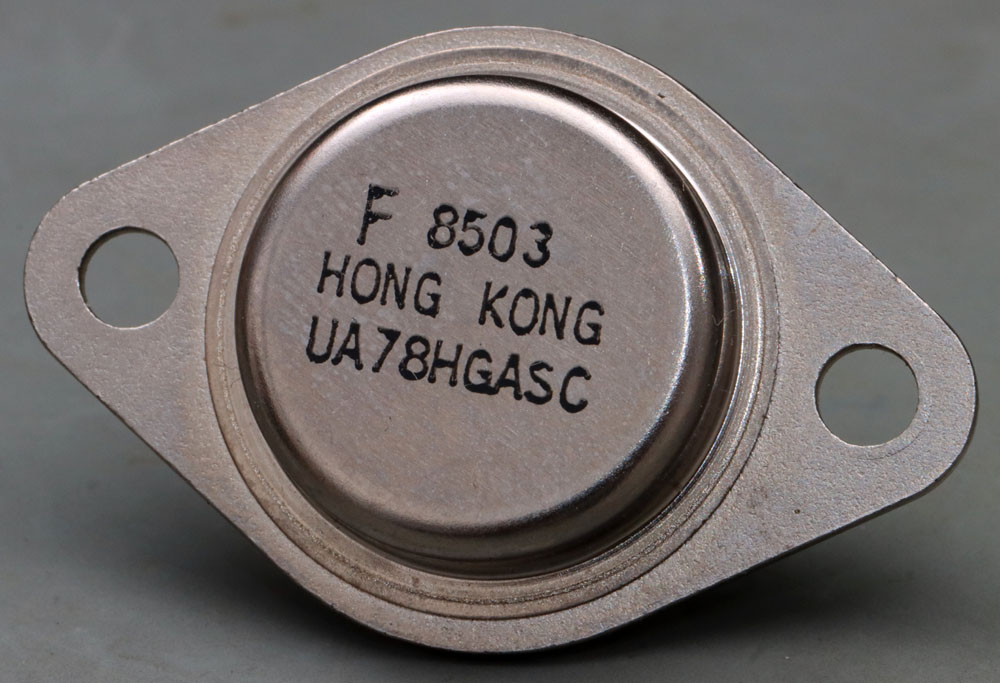
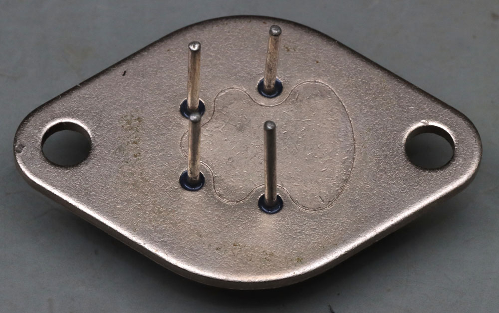
Here you can see the A variant of the µA78HG voltage regulator. In comparison with the µA78HG from 1979 and the µA78HG from 1980, a modern TO-3 housing was already used here. A pressed-in heatspreader can be seen on the underside. Pressed-in heatspreaders are rarely found on modern TO-3 cases. The curved shape is very unusual. This is probably the only way to achieve the necessary thermal conductivity.
The heat spreader is necessary because the base plate of modern TO-3 enclosures is significantly thinner and therefore does not distribute the heat sufficiently over the cooling surface.
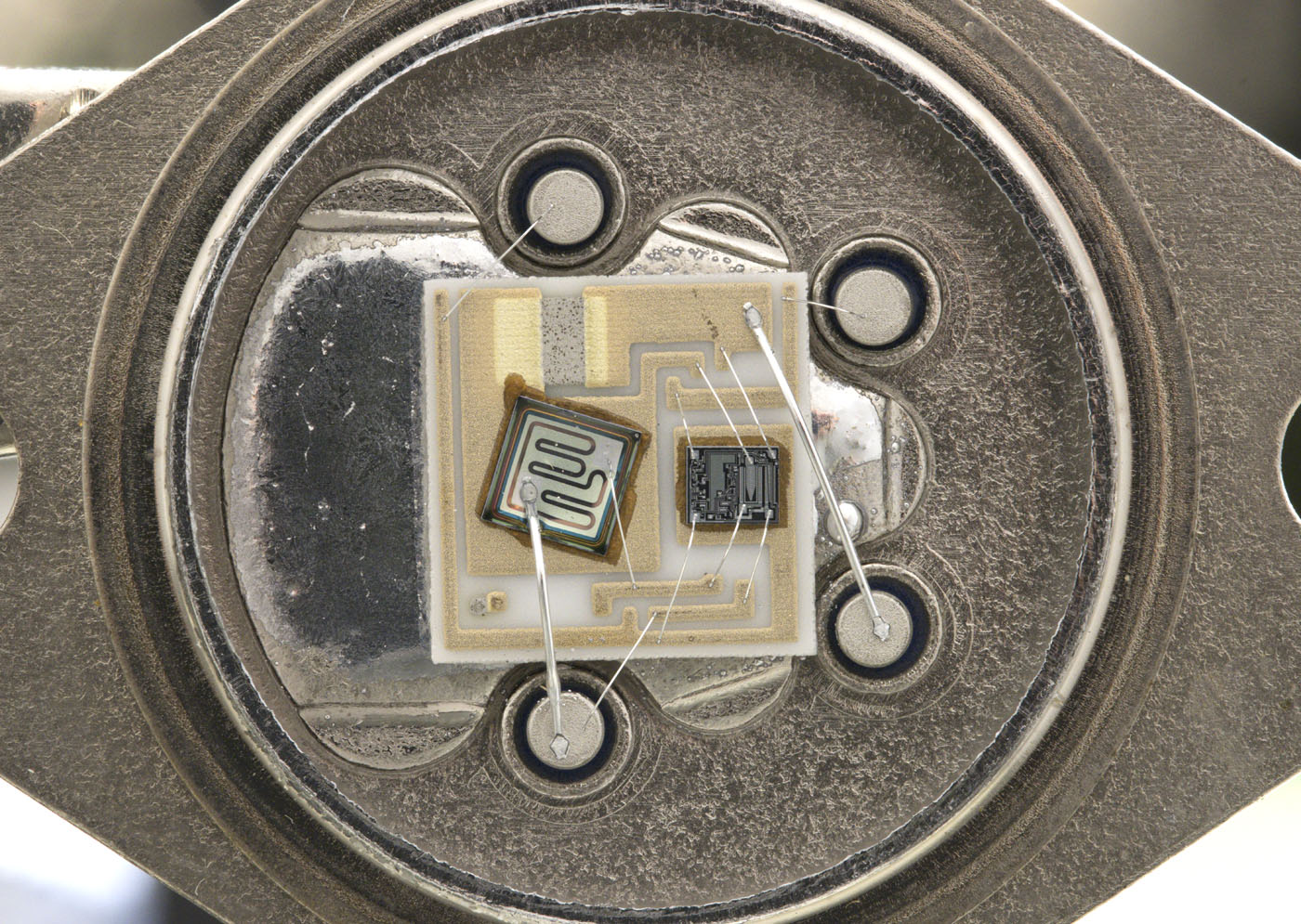
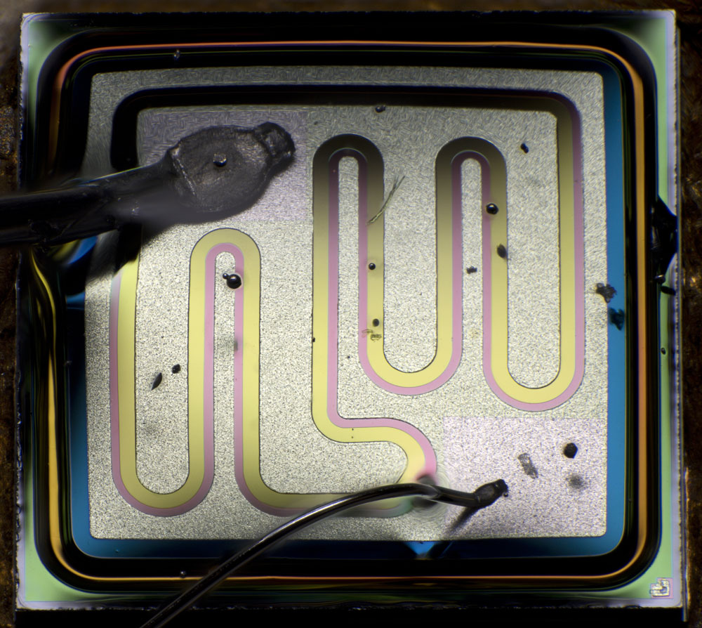
Like the other µA78HG, the µA78HGA also contains a ceramic carrier. In the µA78HGA, thicker bondwires were only used where they were necessary. Thinner bondwires were used where lower currents flow.
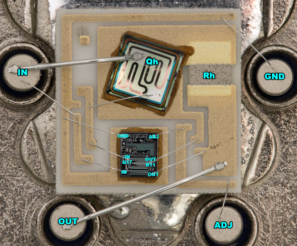
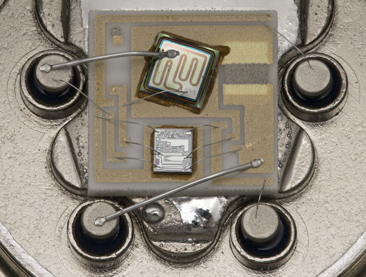
The power transistor is visually similar to the power transistor in the µA78HG from 1980. One major difference in the A variant is the shunt resistor Rh, which is used to limit the current. In the µA78HG, a conductor track of the ceramic carrier was used for this purpose. Here a grey resistor material was used.
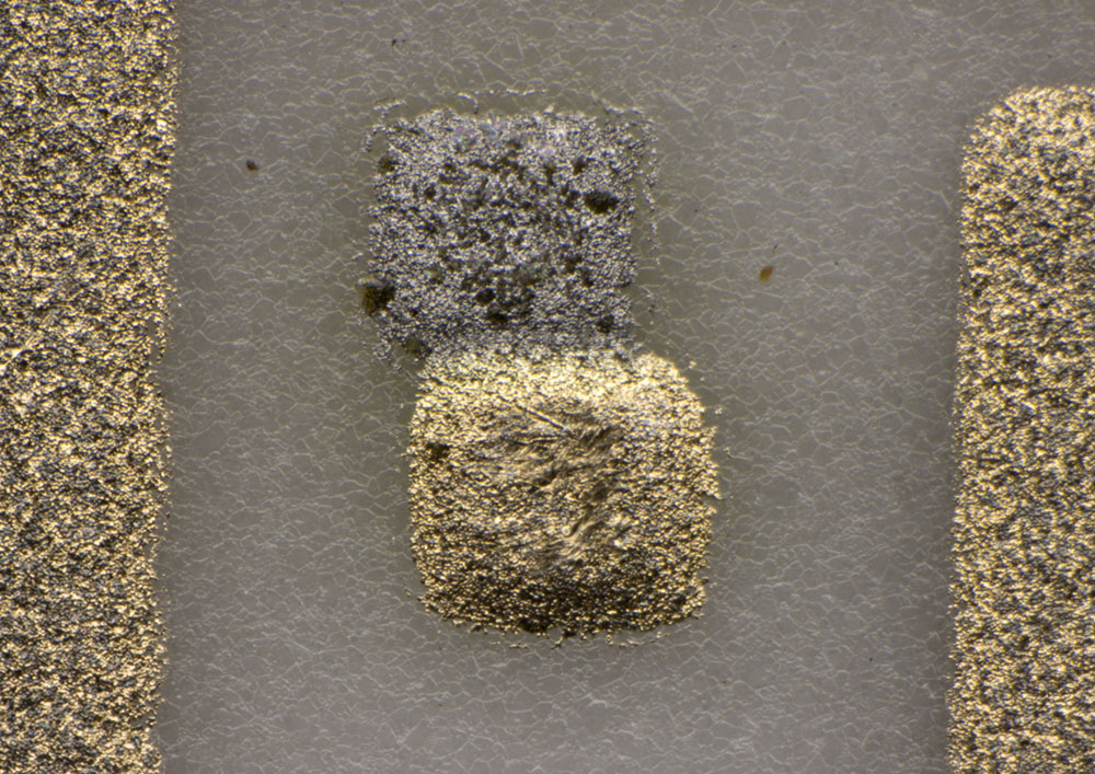
The use of the resistor material has probably made it easier to achieve the desired resistance value. However, the ceramic carrier must be coated with two materials to achieve this. Two squares in the top left-hand corner show how well the resistor material and the metal layer are aligned with each other.
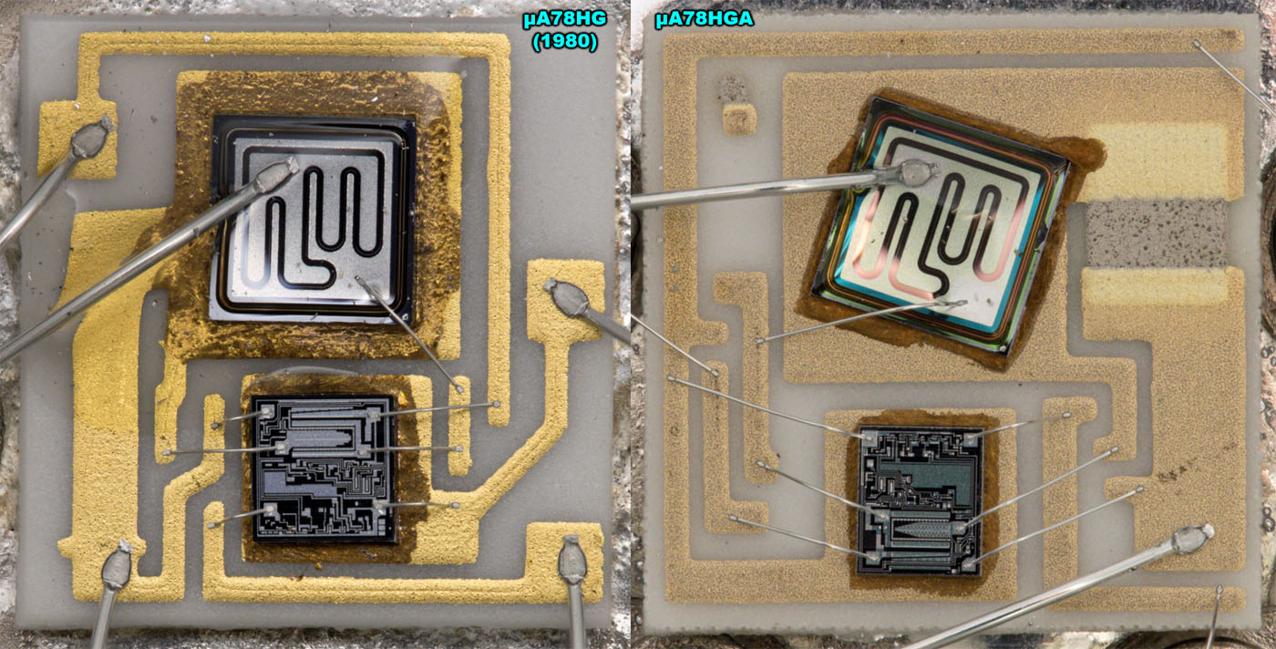
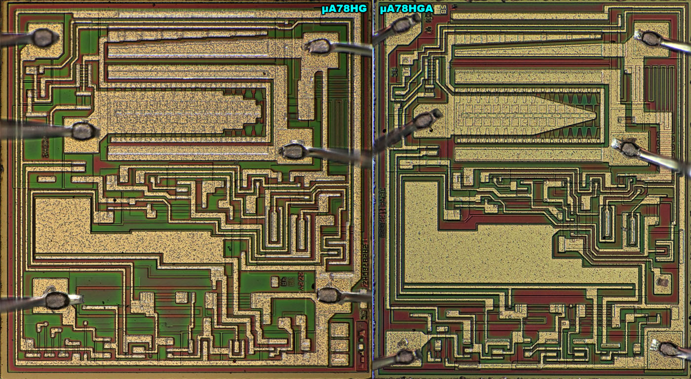
A direct comparison of the µA78HG from 1980 with the µA78HGA shows that the layout has been completely revised. In this context, the controller die has also been rotated by 180°.
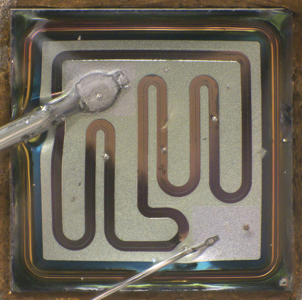
The power transistor is the same type as in the µA78HG from 1980.
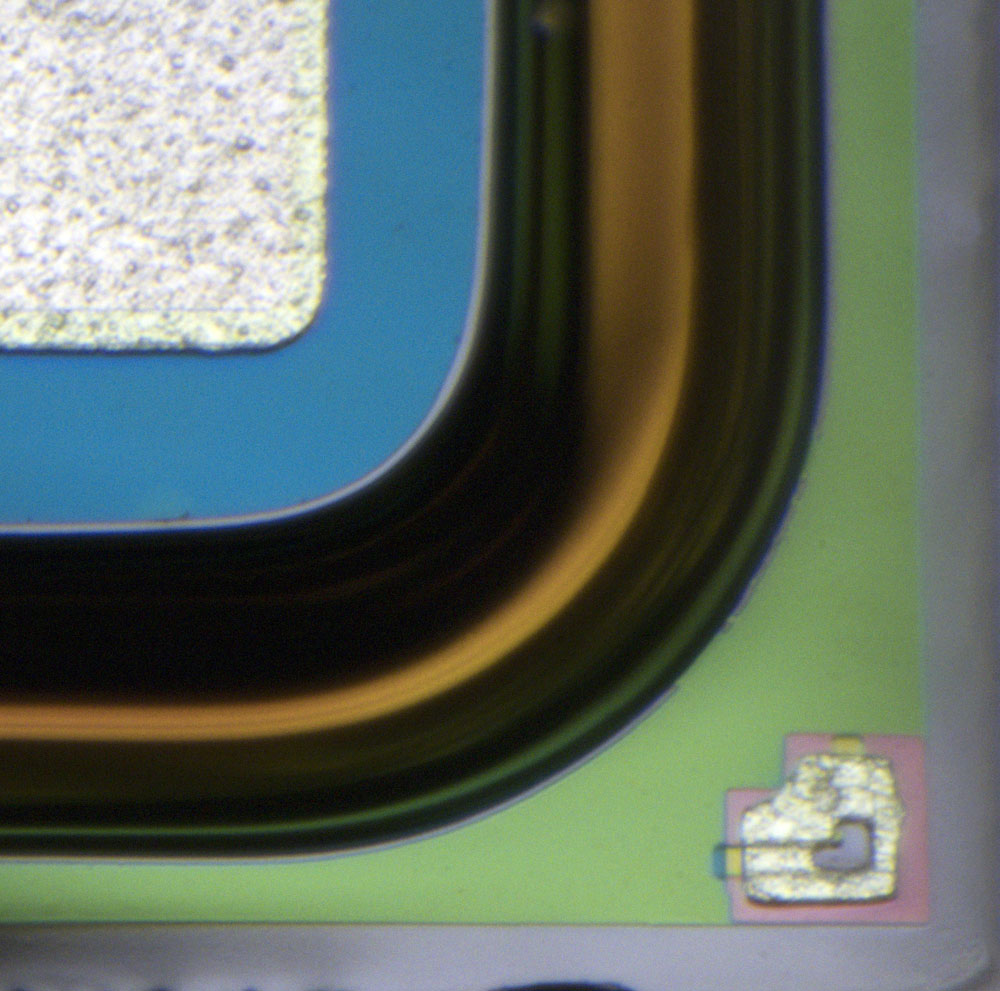
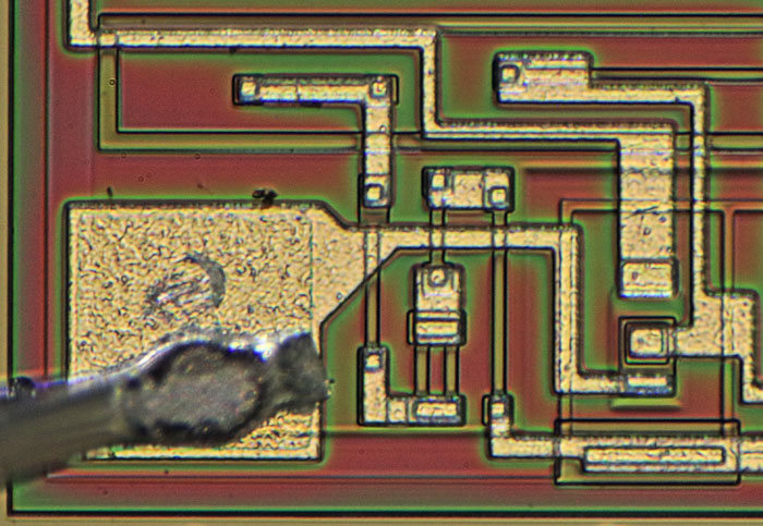
There is an interesting test structure in the bottom right-hand corner of the transistor that can be used to check the alignment of the masks.
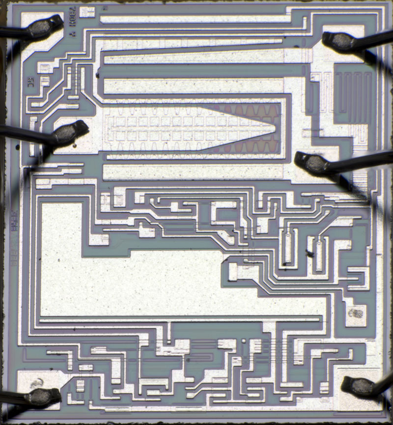
The dimensions of the integrated regulator are 1,6mm x 1,9mm. It is therefore noticeably smaller than the controller type used in the µA78HG from 1979 and the µA78HG from 1980 (1,8mm x 1,9mm).
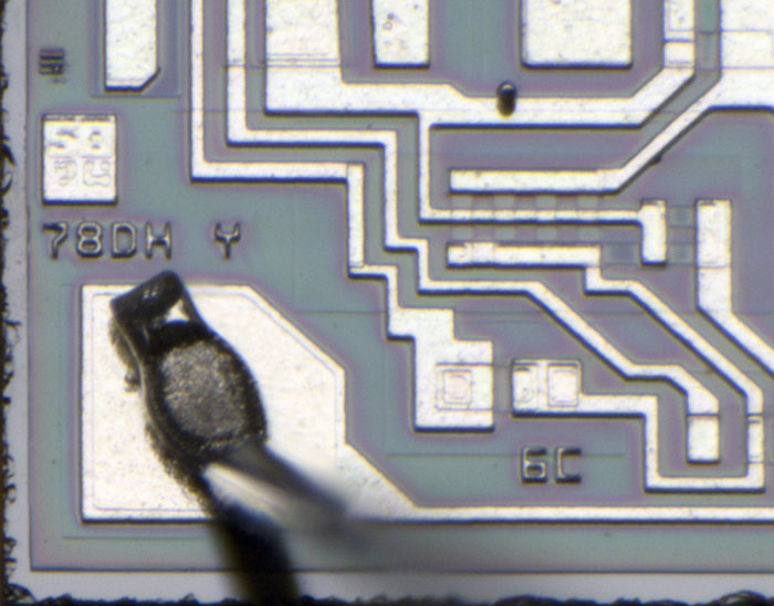
The die shows the letters 78DH Y. The controllers of the older µA78HG were labelled 78DHZ. Apparently the revisions were counted backwards from the letter Z in the direction of A.
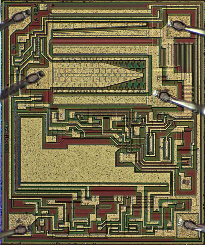
If you place revisions Z and Y directly next to each other, you can see that the circuits are essentially the same.
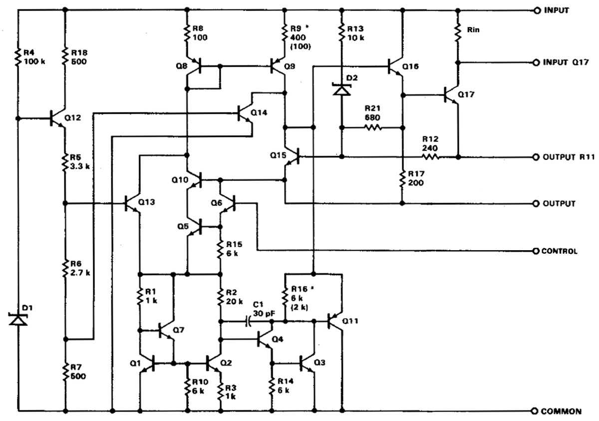
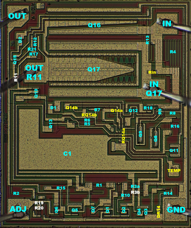
A closer look reveals some minor differences. In the lower right-hand area, the TEMP testpad now offers the option of measuring the potential at the base of transistor Q14. This can be used to determine when the overtemperature protection kicks in. This is helpful as this function is heavily dependent on the tolerance of the resistors.
An emitter resistor has been added to transistor Q14b in the circuit. The capacitance C1 has been made larger. The resistor R3, which consists of two elements, defines the proportion of the negative temperature coefficient in the reference voltage generation. In contrast to the older revision, the resistor R3b is not included in the circuit here.
There are some unused resistors in the bottom left-hand corner, which scale the feedback of the output voltage appropriately for fixed-voltage regulators. There are significantly fewer resistors here than in the previous revision. The ends of some resistors are widened so that their values can also be changed by moving the contact.
https://www.richis-lab.de/voltageregulator26.htm 


