Author Topic: USB C circuit design  (Read 6235 times)

0 Members and 2 Guests are viewing this topic.

Offline tyguy2Topic starter

  • Supporter
  • ****
  • Posts: 303
  • Country: us
USB C circuit design
« on: January 14, 2020, 04:55:47 am »
Hello all,

I'm designing a device that connects a mSATA drive to either a computer via USB 3 or an Android/ iPhone device. After doing some research, I found a USB 3 to SATA bridge IC from TI called the TUSB9261. However, the Android devices we're targeting use the USB C connector, and the iPhones would be using a lightning to USB C adapter. This has presented me with a few questions I need help answering.

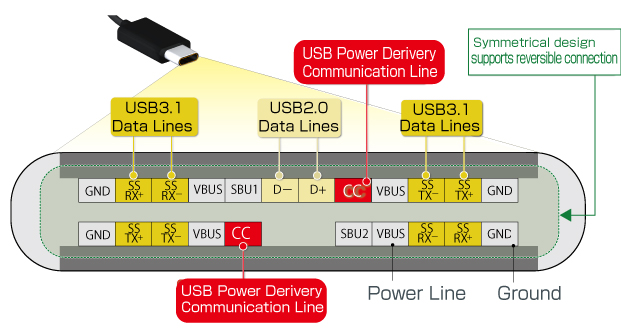
1.) Would I be able to connect the USB 2.0 and USB 3.0 lines from the TUSB9261 directly to the USB C port? (see below)


2.) The iPhone adapter specifies that it adapts lightning to "USB C or Thunderbolt 3." As I understand it, Thunderbolt 3 is "compatible" with USB 3.0, but does that mean I can directly connect the TUSB9261's USB 3.0 lines to this adapter, or do I need some kind of "Thunderbolt 3 to USB 3" bridge? 

3.) Is there an easier way of doing all of this? I feel like there has to be some kind of single chip solution for this type of application. This chip needs firmware on SPI flash, etc, etc, and I see things similar to this done in far less complicated devices. Any ideas are very welcome.

Thanks for your time, I appreciate any answers!
[Sarcastic comment] clever joke [/sarcastic comment]
Bitcoin:
12oV4dWZCAia7vXBzQzBF9wAt1U3JWZkpk
 

Offline ejeffrey

  • Super Contributor
  • ***
  • Posts: 3820
  • Country: us
Re: USB C circuit design
« Reply #1 on: January 15, 2020, 06:23:35 pm »
I am not a super expert in USB3 or type-C so I definitely could be wrong here, but this is my understanding.

First, the easy part: thunderbolt 3 is implemented as an "alternate mode" for USB-C.  So AFAIK, all thunderbolt ports are also USB 3 and you don't need any sort of adapter.

For the type-C things are more complicated.  For USB 2 it is easy: you just wire up the signals to the relevant connector pins and be on your way.  All of the USB2 signals are duplicated on the socket and you just have to connect both up.  You need to wire up the CC pins with the right terminating resistors, but that is it.

For USB3 it is harder.  There are 2 sets of super-speed pins on the socket, but the cable only has one pair of wires in each direction.  You can't wire up the opposing pairs in parallel like you do with the lower speed lines since that will mess up the signal integrity.  So the solution is that a type-C port needs to use the CC pins to detect the cable orientation and uses switches to MUX between the two possible locations.  There are chips that do this from the usual vendors. Just search around for USB type-C controllers.

USB 3.2 can use both sets of contacts to implement two lanes in each direction for double the bandwidth.


Share me

Digg  Facebook  SlashDot  Delicious  Technorati  Twitter  Google  Yahoo
Smf