Hi guys n gals

I've been working on a project and need to find a ways to generate a single short pulse each time a button is pressed.
The pulse is needed to drive an N channel mosfet gate which controls a rail for a high current LED and though this is my first experience with them, I started with the obligarory 555 since they were made for just this purpose.
However, I have a habit of wandering into the unconventional and ended up purchasing Micrel's version of the 555 which come in a 5 pin SOT-23 package as I liked the simplicity that comes with the reduced pin count.
Here's Micrel's schematic for the MIC1555:

Now, I'd like the one shot to work in tandum with a WT588D-16p audio playback module (set to manual operation mode), which in this case, is also a 5v negativly triggared device, so it's a simple case of connecting the trigger pin to the positive side of the "key" pin's pushbutton which in theory, will activate both devices at the same time.
Here's a schematic of the basic setup:

The sinker here I discovered, is the duration of the button press itself, being of the analogue persuation. The datasheet states that the 555's output pin will be prevented from returning to a low state until the trigger pin returns to a high state and as the pulse is calculated for about 1/3rd of a second, it's not likely that the manual press duration will ever be shorter (see attached data sheet for full details).
One thought I had to solve this problem was to drop a PMOS in series with the button and the trigger pin, then tap the 555's outout to operate the gate:

In this scenario, the button would be disconnected whenever the outout goes high, however, I have a suspicion that the interaction between the PFET and trigger will cause the circuit to oscillate as long as the button is held down.
More search refining eventually turned up a website which host a plethora of circuit designs for all kinds of things, including a whole page of them based around the 555.
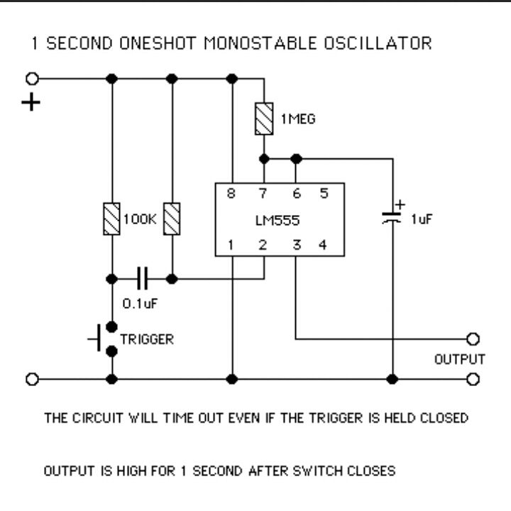
One of which looks to be exactly what I'm after as it's been designed so the input and output are independent of each other once the button has been pressed:

Heres a link to the relevant page on the website, the circuit above can be found near the bottom of the page:
[url=http://www.bowdenshobbycircuits.info/page9.htm]http://www.bowdenshobbycircuits.info/page9.htm] [url]http://www.bowdenshobbycircuits.info/page9.htm]http://www.bowdenshobbycircuits.info/page9.htm]http://www.bowdenshobbycircuits.info/page9.htm] [url]http://www.bowdenshobbycircuits.info/page9.htm[/URL]
And finally, here is my attempt at translating the above circuit for the MIC1555:

I'm a little unsure its totally right as I'm not the best at schematic interpretations and drawing so would really appreciate someone casting an eye over it.