Regarding someone having 'scoped the mains (utility) waveform, this is a very interesting recording I made in July 29, 2012:
Ch1 reading directly my home's mains power outlet, and Ch2 reading whatever electrical signals existed in the air by using the ~3cm probe tip extension as an aerial:
[...]
Now, here is an interesting waveform I captured, using my 100 MHz DS1052E:
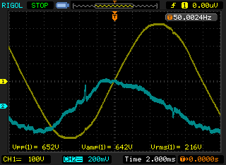
Ch1 to the mains line; Ch2 floating
Channel 1 was reading the mains voltage directly1, using a 100x probe, and
Channel 2 was reading whatever it could pick up while unconnected, using the standard 10x probe, floating.
Please note that it made no difference at all turning ON or OFF the 75W monitor (a DELL U2410) right in front of me, or the 250W halogen roof lamp (driven by a traditional and noisy phase-control TRIAC dimmer), or the 1.3KW room air-conditioning unit (the thermometer outside my window now reads 37 deg.C!). The captured waveforms were exactly the same, either the noisy units above were powered on or off.
For those who will notice it, the mains voltage was externally measured to be 228.7 VAC RMS, while the DS1052E measured it to be 218 VAC RMS (DS1052E error: -4.7% or -3bit); in defence of the DS1052E, I will have to state that I did not warm it properly up before taking these readings, neither have I recently run auto-calibration2.
The interesting parts in the captured waveform above are the time points -1.7div (-3.4 ms) and +3.3div (+6.6 ms), where Ch1 captures a couple of seemingly innocuous mains disturbances, which are absolutely synchronised to the Ch2 obvious spikes. The problem is that, though the Ch1 and Ch2 waveforms are out of synch by ~1.4div (~2.8 ms), the Ch1 and Ch2 spikes are in perfect synchronisation. Channel crosstalk, do I hear some of you murmuring? Well, maybe. But, by disconnecting the Ch2 probe, the second trace became a nice and clean flat line while the spikes at the first trace remained as they were exactly, and of the same shape and amplitude. So, I suppose that my scope is not really lying to me...
This means that:
1. The depicted spikes are probably generated erroneously within the oscilloscope front-end amplifiers.
2. Our mains lines are actually that dirty.
3. We are both being bombarded by who-knows-what kind of electromagnetic weapons  (I am kidding!).
What I can only say is that, in order to trust what my DS1052E tells me about my mains line spikes, I would have to repeat those readings with a higher class oscilloscope and not with another entry-level one.
EDIT:
1. DO NEVER TRY doing that if you are not absolutely sure of what you are doing, because the probe ground clip is the instrument's ground, which is hardwired to the mains power supply ground! Be very careful when messing with the mains line.
2. More than half an hour later, the mains line was reported by the DS1052E to be 221 VAC RMS, while it was measured to be 223.2 VAC RMS.
-George
I remember reading about some PLC standard that outputted pulses similar to that.
A modified square wave inverter is plenty for general purpose use. Most electronics don't really mind it (the peak current is actually lower than with sine waves, and even lower with a square wave of the same peak voltage) and motors run noisy but rarely have problems. (The Prius inverter actually outputs square waves at higher speeds where noise is not an issue.) While the fancy sine wave drive computer fans are more efficient than the cheap square wave type, that's actually because they use FOC, which an off the shelf sine wave inverter will not do.
The EMI and standing wave issues can be solved by adding series inductance at the inverter. A passive PFC choke out of an old PC PSU works well. If it's only for running switching power supplies, you can open it up and there'll often be a trimpot to increase the output duty cycle to the point where it's almost a square wave,, along with another trimpot that lets you turn down the frequency.
What I would like to see in an off the shelf "smart" inverter is V/Hz soft starting/overload avoidance and automatic load characterization. For example, if it detects only a rectifier type load, it turns the output frequency way down and the duty cycle up in order to cut losses. The moment it detects a motor or transformer load, it quickly changes back to V/Hz operation.


