Author Topic: Some 555-Timer-Dies  (Read 40886 times)

0 Members and 2 Guests are viewing this topic.

Offline NoopyTopic starter

  • Super Contributor
  • ***
  • Posts: 1880
  • Country: de
    • Richis-Lab
Re: Some 555-Timer-Dies
« Reply #75 on: November 21, 2020, 07:23:15 pm »
Finally the soviet NE555, the КР1006ВИ1 (KR1006VI1):


You can find a datasheet written by Alfa but I assume the КР1006ВИ1 was built by more soviet manufacturers.
The design is different to any die I have decapped until now.
In the upper right corner of the labeling there are four diodes leading to a long resistor. The string is connected between supply and ground. It looks like the potential between diodes and resistor is used for a kind of biasing in the trigger differential amplifier. That´s something I haven´t seen in any other NE555.

https://www.richis-lab.de/555_36.htm

 :-/O
 
The following users thanked this post: SeanB, serg-el

Offline NoopyTopic starter

  • Super Contributor
  • ***
  • Posts: 1880
  • Country: de
    • Richis-Lab
Re: Some 555-Timer-Dies
« Reply #76 on: April 13, 2021, 06:58:41 pm »


That´s the oldest NE555 I have.


It seems like a silicone mold. It was very hard to remove.
On surface of the die there is something like a protection layer.


The die is quite similar to the newer Signetics NE555 but...


There is one difference. In the older design Q10/Q11 are acting like a darlington transistor. In the newer designs Q10 is connected to ground. In addition Q11 is a current mirror which is not mentioned in the datasheet.
I assume connecting Q10 to ground makes the trigger circuit switching faster but why that current mirror?  :-//


https://www.richis-lab.de/555_6.htm

 :-/O
 
The following users thanked this post: SeanB

Online magic

  • Super Contributor
  • ***
  • Posts: 7130
  • Country: pl
Re: Some 555-Timer-Dies
« Reply #77 on: April 14, 2021, 07:04:27 pm »
It's nothing special, just additional bias for Q10, perhaps to speed it up or reduce its output impedance or whatever. And grounding its collector enables the comparator to function all the way down to ground like LM358.
 

Offline NoopyTopic starter

  • Super Contributor
  • ***
  • Posts: 1880
  • Country: de
    • Richis-Lab
Re: Some 555-Timer-Dies
« Reply #78 on: April 15, 2021, 03:07:39 am »
It's nothing special, just additional bias for Q10, perhaps to speed it up or reduce its output impedance or whatever. And grounding its collector enables the comparator to function all the way down to ground like LM358.

I assume the grounded collector gives you some more switching speed too. A little more Vce, a little more Ic. A little more Ic, a little faster switching of Q11. What do you think?

Regarding the current mirror: Isn´t it a drawback that the current mirror eats up half of the current which otherwise could switch the next stage with more current (=more speed)?

Online magic

  • Super Contributor
  • ***
  • Posts: 7130
  • Country: pl
Re: Some 555-Timer-Dies
« Reply #79 on: April 15, 2021, 06:41:31 am »
Not a problem if total Q11+Q12 current is set appropriately. Some LM358 use this exact scheme on their Q10/Q13, while others have dedicated current sources.

It doesn't seem clear if it's exactly 50% of the current being redirected here.
« Last Edit: April 15, 2021, 06:44:53 am by magic »
 
The following users thanked this post: Noopy

Offline David Hess

  • Super Contributor
  • ***
  • Posts: 17089
  • Country: us
  • DavidH
Re: Some 555-Timer-Dies
« Reply #80 on: April 16, 2021, 02:49:44 am »
The current mirror allows Q10 to operate at a higher collector current for better performance.

Not a problem if total Q11+Q12 current is set appropriately. Some LM358 use this exact scheme on their Q10/Q13, while others have dedicated current sources.

The datasheet schematics often leave those details out.

Quote
It doesn't seem clear if it's exactly 50% of the current being redirected here.

That depends on the emitter ratios which are only rarely documented.
 
The following users thanked this post: Noopy

Online magic

  • Super Contributor
  • ***
  • Posts: 7130
  • Country: pl
Re: Some 555-Timer-Dies
« Reply #81 on: April 16, 2021, 06:28:07 am »
That depends on the emitter ratios which are only rarely documented.
Or the collectors ;)

And an example seen in the wild: 75% of input pair current goes to the buffers; this also takes care of the "transconductance reduction" thing.
https://zeptobars.com/en/read/ST-TS321-SOT23-opamp-LM358A-LM324
 

Offline NoopyTopic starter

  • Super Contributor
  • ***
  • Posts: 1880
  • Country: de
    • Richis-Lab
Re: Some 555-Timer-Dies
« Reply #82 on: April 16, 2021, 03:30:18 pm »
Thanks for your explanations.  :-+
I remember the transconductance reduction!  :-+ :)

Offline David Hess

  • Super Contributor
  • ***
  • Posts: 17089
  • Country: us
  • DavidH
Re: Some 555-Timer-Dies
« Reply #83 on: April 17, 2021, 04:13:27 pm »
I remember Bob Pease's comment about how they documented emitter area:

Maybe I should explain about the "ranchette.”  The "ranchette" is a unit of area defined as 1/2 pico-acre.  The ranchette is exactly the size of a round emitter 1 milli-inches in radius (well, 0.9983 milli-inch), so it really is handy when dealing with large matched pairs of transistors.
 

Offline NoopyTopic starter

  • Super Contributor
  • ***
  • Posts: 1880
  • Country: de
    • Richis-Lab
Re: Some 555-Timer-Dies
« Reply #84 on: October 24, 2021, 03:39:30 am »


I have added a Ti NE555 bought 2020.


(Yes, Zeptobars has taken a better picture. I have had some problems with the package.)
We have seen the A and the B design and here we have the D design. There has to be a C design somewhere. Perhaps they didn´t sell the C revision or we still have to find it.
Ti did a complete redesign. They still use the power transistors with the small emitters which aside from Ti just Rohm has used (https://www.richis-lab.de/555_25.htm).


https://www.richis-lab.de/555_10.htm

 :-/O


Back in the days I wasn´t sure about the "other design" I found just in some Ti-NE555. I was speculating that perhaps Ti did a very cheap redesign. I have changed my mind. They are probably counterfeit parts and now can be found here:  https://www.richis-lab.de/555_37.htm
 
The following users thanked this post: SeanB

Offline NoopyTopic starter

  • Super Contributor
  • ***
  • Posts: 1880
  • Country: de
    • Richis-Lab
Re: Some 555-Timer-Dies
« Reply #85 on: November 13, 2021, 04:27:49 am »


КP1441BИ1 (KR1441VI1), a CMOS-NE555 built by Mikron.


On the left edge of the die there is the big push-pull output. On the right side we see the discharge transistor. In the middle of the die you can spot the three long resistors which are typical for the NE555.


https://richis-lab.de/555_38.htm

 :-/O
« Last Edit: November 13, 2021, 08:22:42 am by Noopy »
 
The following users thanked this post: SeanB

Offline NoopyTopic starter

  • Super Contributor
  • ***
  • Posts: 1880
  • Country: de
    • Richis-Lab
Re: Some 555-Timer-Dies
« Reply #86 on: August 23, 2024, 10:05:15 am »


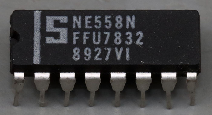
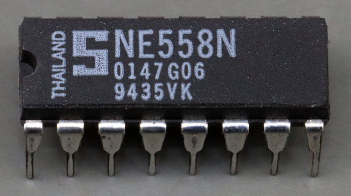
Signetics had a quadruple timer in its program: NE558. However, these are not four complete NE555. The DIL16 package would not be sufficient for four complete NE555.


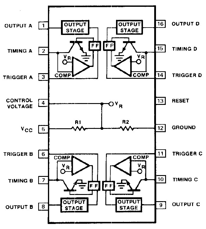
All four timers share a voltage divider, which is used as a reference signal for the comparators. In the four timer blocks, the discharge transistor is connected directly to the comparator. The NE555 has a push-pull output stage. The NE558, on the other hand, only has a lowside transistor. There is also a NE559, which is equipped with a highside transistor at the output.


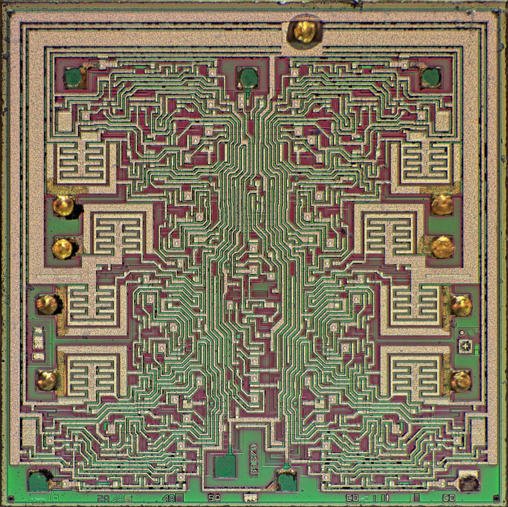
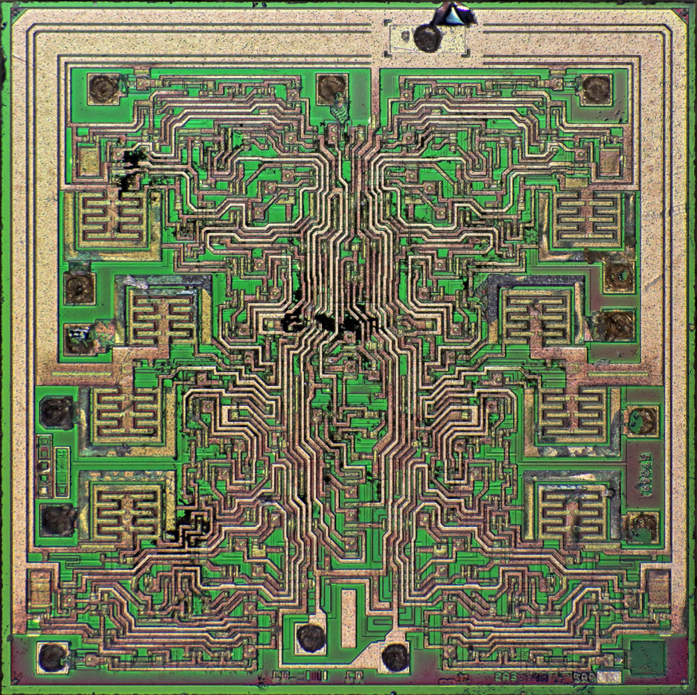
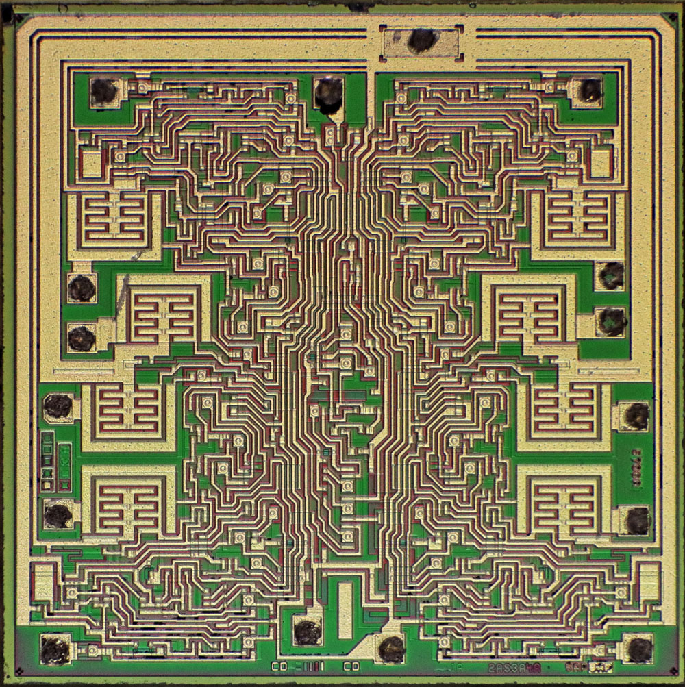
The edge length of the die is 2,4 mm. The four-part circuit is clearly recognizable. In contrast to the NE555 (https://www.richis-lab.de/555_6.htm), each section contains only two of the distinctive power transistors.


The NE558 shown here was produced in 1993 and is therefore somewhat more up-to-date than the first variant.


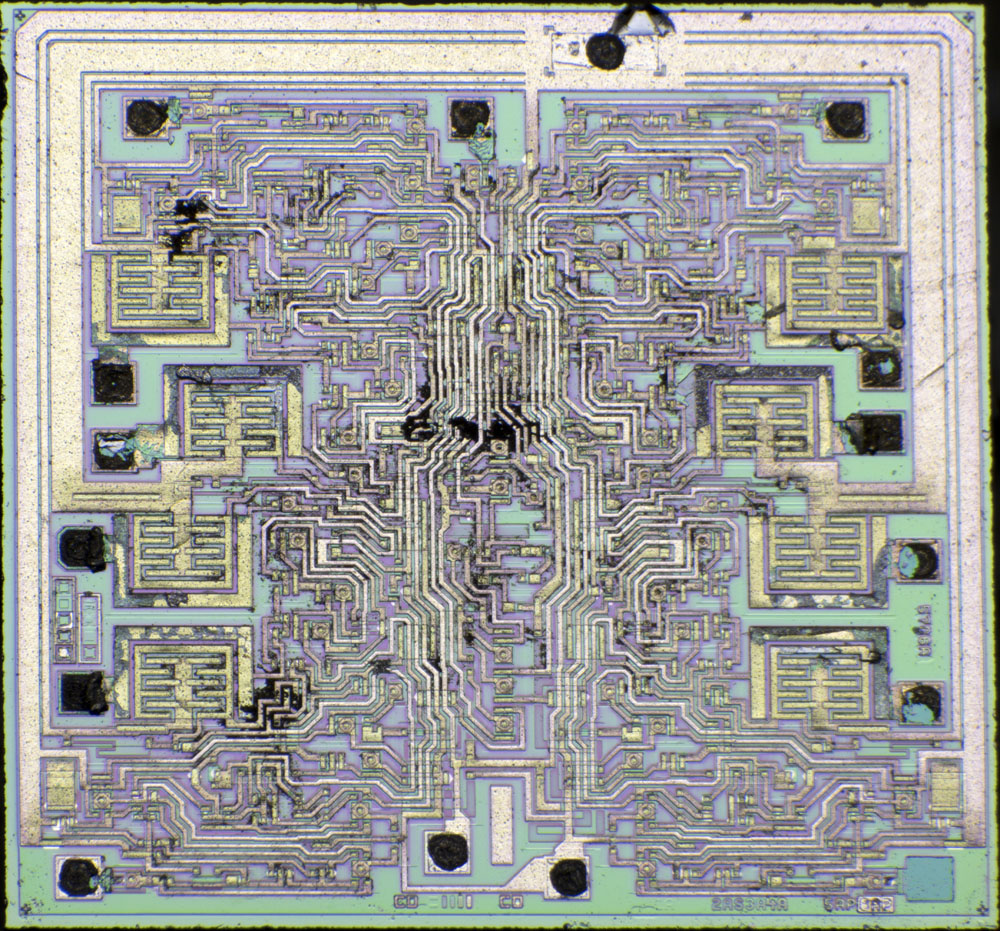
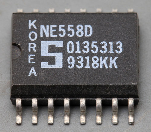
This NE558 has a different design. The auxiliary structures, the designation and the mask revisions have changed. The bondpads have also been placed slightly differently.


With a datecode from 1994, this NE558 is the newest of the three modules.


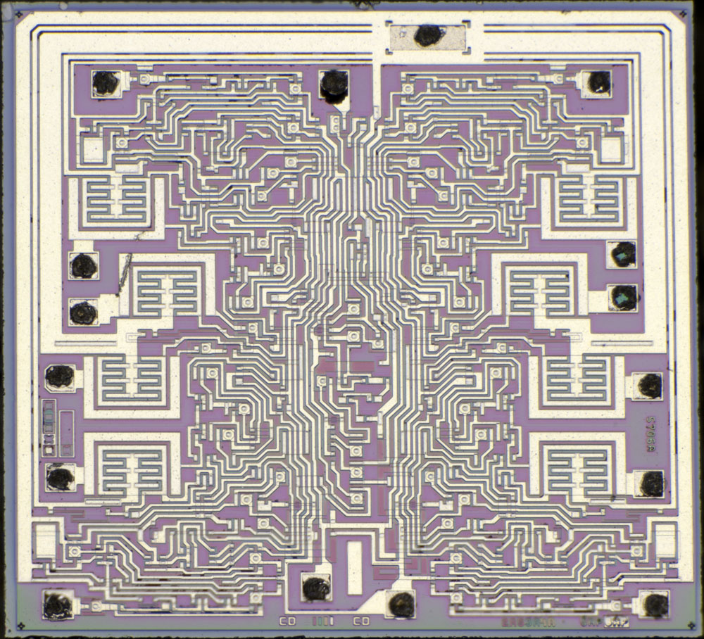
It features the same updated design as the NE558 from 1993, which could be extracted more cleanly from the housing material.


https://www.richis-lab.de/555_40.htm

 :-/O
 
The following users thanked this post: SeanB, iMo

Offline iMo

  • Super Contributor
  • ***
  • Posts: 5124
  • Country: bt
Re: Some 555-Timer-Dies
« Reply #87 on: August 23, 2024, 10:22:32 am »
This 558 would not work the same way as the 555 does.. The trick with a good 555's stability independent on the Vcc is the usage of 3 resistors in the divider with 2 comparators..
 

Offline NoopyTopic starter

  • Super Contributor
  • ***
  • Posts: 1880
  • Country: de
    • Richis-Lab
Re: Some 555-Timer-Dies
« Reply #88 on: August 23, 2024, 10:24:41 am »
This 558 would not work the same way as the 555 does.. The trick with a good 555's stability independent on the Vcc is the usage of 3 resistors in the divider with 2 comparators..

Yes, it´s not a "four NE555" it´s a "four timer circuits".
It doesn´t deserve the name similarity.
 
The following users thanked this post: iMo


Share me

Digg  Facebook  SlashDot  Delicious  Technorati  Twitter  Google  Yahoo
Smf