Author Topic: Help figure out this power supply for uv lamp from water purification system  (Read 376 times)

0 Members and 1 Guest are viewing this topic.

Offline crossorb93Topic starter

  • Newbie
  • Posts: 2
  • Country: ca
Just for fun I thought I would figure out the workings of this power supply for a consumer water purification device which features a ~30W uv lamp.  It failed and I got a new one so I'm free to take it apart.  Most of it seems straighforward but I have a couple of questions.

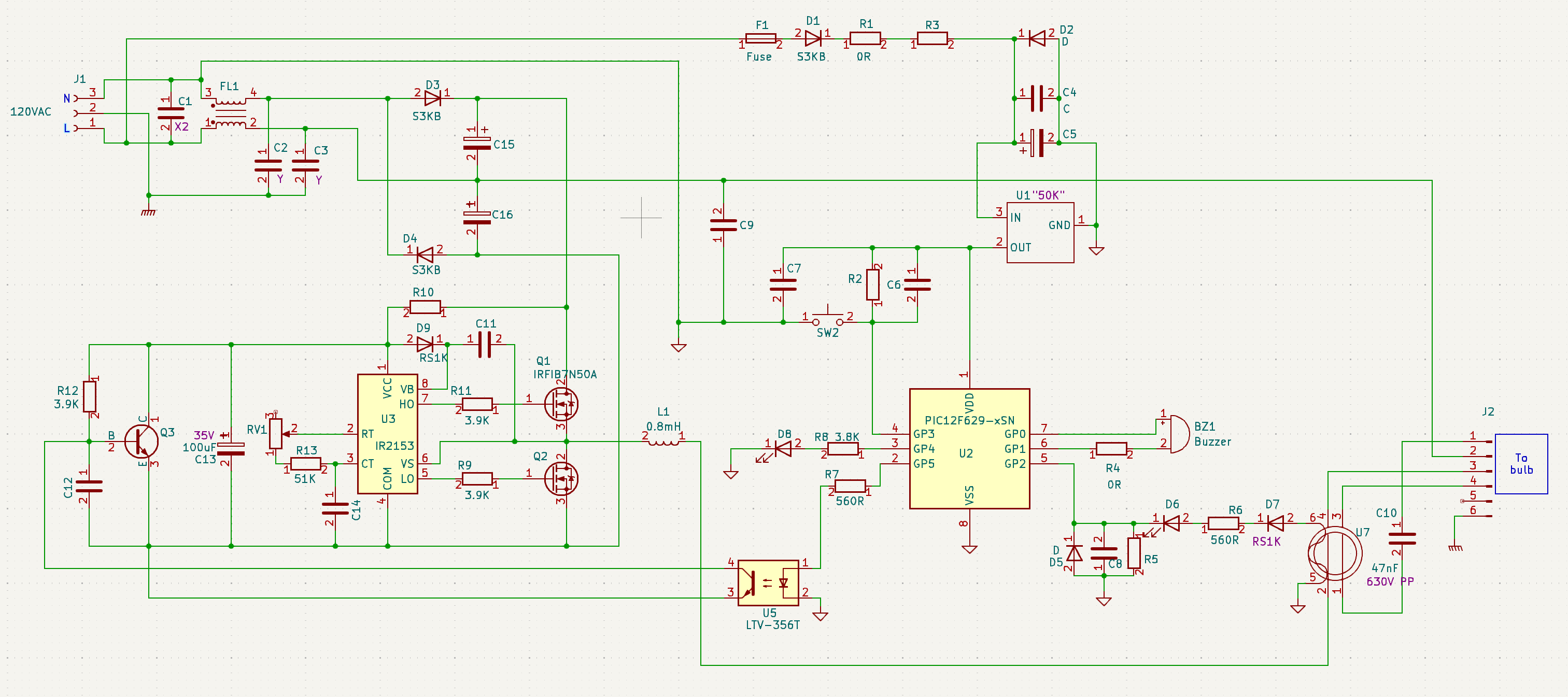
The PIC microcontroller is powered by a SOT23-3 chip marked "50K".  Anyone know what this might be?  It looks like it might be a voltage regulator.  It's powered from the AC line input through a large resistor and a diode.  The IR2153 is powered in a similar way but it has an internal zener that clamps vcc to 16V.  Would this little chip have something similar or have I missed something in the circuit?

The other question relates to the 4 connections to the lamp.  One wire gets the square wave from the power mosfets after smoothing by a 0.8mH inductor.  Another is ground.   The third and fourth wires are connected by a capacitor.  I don't understand why there are two wires going through the current sense transformer.  How does this bulb work and what is the function of the third and fourth wires?

« Last Edit: September 09, 2024, 02:27:33 am by crossorb93 »
 

Online moffy

  • Super Contributor
  • ***
  • Posts: 2073
  • Country: au

The other question relates to the 4 connections to the lamp.  One wire gets the square wave from the power mosfets after smoothing by a 0.8mH inductor.  Another is ground.   The third and fourth wires are connected by a capacitor.  I don't understand why there are two wires going through the current sense transformer.  How does this bulb work and what is the function of the third and fourth wires?


I would guess that the tube has heater filaments, hence the 4 wires, two through the current transformer would double its sensitivity. I would also assume that it is resonant, hence the inductor and capacitor are producing something approaching a sine wave and the resonance or Q is producing the voltage multiplication.
« Last Edit: September 09, 2024, 06:50:17 am by moffy »
 

Offline crossorb93Topic starter

  • Newbie
  • Posts: 2
  • Country: ca
Thanks, that gives me some reading to do.

With no starter, how does this system produces the initial large voltage spike to strike the arc?
 

Online IanB

  • Super Contributor
  • ***
  • Posts: 12356
  • Country: us
I think some lamps don't necessarily need a high voltage to start. Heated filaments can emit enough electrons to start a discharge going without a high voltage across the tube. Once the discharge is operational, the heated filaments can be disconnected.
 
The following users thanked this post: moffy

Online moffy

  • Super Contributor
  • ***
  • Posts: 2073
  • Country: au
With no starter, how does this system produces the initial large voltage spike to strike the arc?

As IanB said also without the discharge the Q of the circuit should be higher, producing a higher starting voltage which would drop when the discharge starts, a negative resistance region or a case of current increasing with decreasing voltage.
 

Online moffy

  • Super Contributor
  • ***
  • Posts: 2073
  • Country: au
The reason for the two wires through the current transformer is, Wire A carries the full load current and Wire B carries the resonant cap current, so my guess is they are subtracting the cap current from the load current to get only the tube current.
 
The following users thanked this post: crossorb93


Share me

Digg  Facebook  SlashDot  Delicious  Technorati  Twitter  Google  Yahoo
Smf