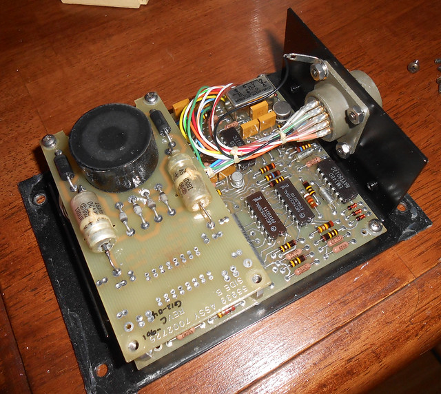
Another broken piece of avionics showed up for pretty cheap and I couldn't resist: it turned out to have some pretty interesting analog computation going on inside.
This is the Honeywell RZ-220 Roll Rate Monitor.

It was manufactured in 1991 but the design looks at least a decade older than that. I'm not even vaguely an aircraft expert or a pilot, but my guess is that it connects to the aircraft's gyroscope (which would show its current pitch, roll, and yaw) and drives some kind of indicator dial and/or warning light based on the rate at which the "roll" reading is changing.
Once the cover is taken off easily by removing 4 screws in the corners, you can see the inside:

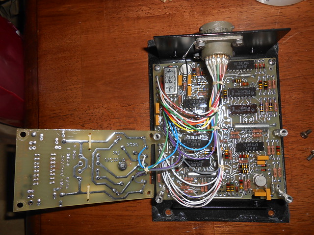
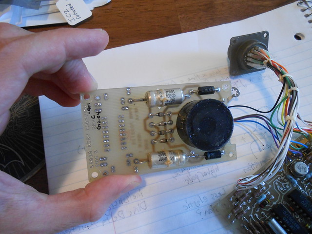
The single external connector is wired to a main board, and a power supply board stacked on top. After unscrewing the mounting screws for the power supply board, you can see the rest of the main board:

There's not much going on with the power supply, so I'll just note that it has a simple transformer / bridge rectifier / bulk capacitors to step down the 400 Hz 115VAC power to a positive and negative DC supply (±12V? ±15V?) and leave it at that.

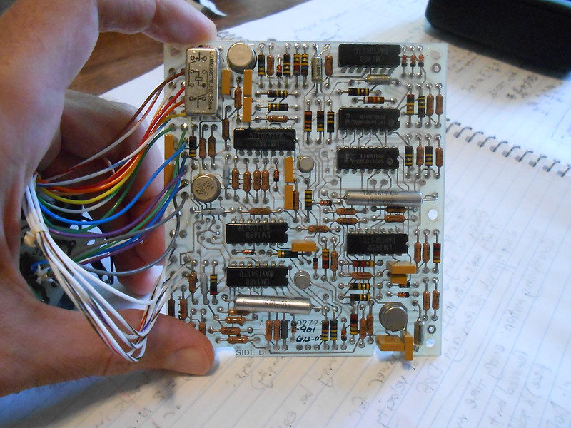
The main board is where all the action happens though. There's 5 different LM148 quad op-amps, an LH0070 10V reference, plus a few other metal-can devices and a relay. The layout is very 70's-style, 2-layer, with no ground planes or anything similar, just traces snaking all over the board:

The board is conformal-coated, but by overlaying photos of the top and bottom, and using sewing needles held in J-clips on my multimeter for continuity testing in a few key places, I was able to figure out this schematic, which I'm pretty confident in except for some of the resistor values:

(Apologies for the messiness in places, such as the very non-standard "cross-over" underneath the op-amp at top right - not power connections, just a jump! Power connections & power filtering are omitted for clarity.)
Background & Gyroscope signal inputMy best guess is that the "roll position" input from the aircraft's gyroscope comes in the form of a synchro signal. You can read more at
Wikipedia, but the basic idea is that you can sense position of a shaft by attaching a coil to it (driven with the single-phase AC aircraft power), and then placing 3 pickup coils around it at 120° intervals. The pickup coils ("stator") will have voltages induced that are either at 0° or 180° relative to the shaft's drive coil ("rotor"), and the amplitude will vary depending on the position of the shaft. By comparing the relative amplitudes of the 3 pickup coil signals, you can unambiguously determine the angle of the shaft.
The section in the top-left of the 1st schematic page seems to be receiving the 3 synchro signals from the gyro's roll sensor. It does some kind of math with linear combinations of the 2 or 3 signals and produces 2 separate outputs. I'm not sure yet exactly what the meaning of these 2 "synchro math" signals from the op-amps are, as I haven't sat down and worked out the math along with the real resistor values to get the scaling right.
/?action=dlattach;attach=1823515;image)
The aircraft's AC power signal (which presumably is also used to drive the synchro system) is also scaled down by a differential receiver:
/?action=dlattach;attach=1823527;image) Sampling & Analog Computing
Sampling & Analog ComputingThe bottom "synchro math" signal is now used by an interesting circuit which compares a peak-detector value against an instantaneous value, which I believe is used to drive the LF156's output high at the peaks of the bottom "synchro math" sinewave.
/?action=dlattach;attach=1823521;image)
This drives the gates of 2 JFETs, which sample both the TOP "synchro math" signal, and the sensed AC power signal, at the peaks of the BOTTOM "synchro math" signal.
/?action=dlattach;attach=1823533;image)
The sampled peaks(?)/valleys(?) of the AC power signal are used in some kind of interesting oscillator which drives some PWM-based math. I think I get the general idea of what it's trying to do, but haven't sat down and worked through the math in detail to confirm.
First, this op-amp-used-as-a-comparator creates an oscillator (because of its hysteresis with the positive-feedback resistors, and the capacitor creating a time delay on the input) that drives a 4053 CMOS analog switch to maintain its input voltage (which is a sum of the sampled AC power signal, and a current source created by a resistor from -10V) around 0V. If you average the voltages and currents in this circuit across the switching cycles, effectively what it's doing is multiplying the (102KΩ to -10V) current source by a scaling factor (the PWM duty cycle of the analog switch's control signal) and using a feedback loop to find the duty cycle that's needed to make all the currents at its input sum to zero. Because one of the input current sources comes from the sampled AC power signal, the PWM duty cycle is going to be some function of the AC power signal's peak(?) value.
/?action=dlattach;attach=1823539;image)
This
same PWM signal is now used to drive a SECOND switch, where it switches a resistor in and out of the feedback path for an op-amp. The large time constant of the resistor and the feedback capacitor across the op-amp (~16 Hz) means that these pulses are likely averaged out, and so this switched feedback resistor is effectively acting as a variable resistor, and creating variable gain on this op-amp.
/?action=dlattach;attach=1823545;image)
This is a very clever way of creating a low-frequency variable gain, without having to use analog multipliers, which are expensive/drifty/etc. The variable gain is applied to the sampled "top synchro math" signal.
Overall, I think the purpose of this whole section is to normalize the synchro's output signal amplitude to the AC power amplitude. After all, what determines the position of the synchro is the amplitude
ratio of each output signal to the drive signal - and the drive signal should not have to be precisely regulated (as it's the general-purpose AC aircraft power) to prevent invalid synchro readings.
This normalized signal, which is likely then proportional to the roll reading, is sent to the connector where it might drives a gauge or other equipment, or just be used for self-test purposes.
Roll RateThis instantaneous-roll signal is then used to check some reasonable bounds:
/?action=dlattach;attach=1823551;image)
First, the roll signal is sent to an op-amp differentiator at the bottom of that image above, which outputs a signal proportional to the roll
rate. This output, as well as the instantaneous roll reading, are then used by some window comparators and simple digital logic, which drive time delays created by RC circuits and comparators. The outputs of these comparators pull down on what looks like a common "fault" signal, that I called "ovr int" here.
The purpose seems to be:
- If roll rate is outside one set of bounds, then activate "fault" after a certain delay
- If roll rate is outside this same set of bounds but the instantaneous roll reading is also outside a certain set of bounds, then activate "fault" after a different delay
The "roll rate" output from the differentiator also goes to a pin on the connector, so this might either drive a "roll rate" gauge, or also just be used as some kind of functionality test for this box.
The "fault" signal drives a mystery metal can that I'm pretty sure is either an op-amp or comparator based on the pinout. It drives a fault output that goes onto the connector via some mystery wiring with the relay. I'm not exactly sure what the relay is for, but it didn't seem worth figuring out that part in detail. Either way, this "fault" signal likely turns on a cockpit indicator that shows the aircraft's roll rate is out of bounds.
Error CheckingThere's some other handling of unusual conditions. First off, there's "loss of signal" detection from the synchro input:
/?action=dlattach;attach=1823557;image)
Whenever the "bottom synchro math" sinewave is below a negative threshold, the left-hand op-amp-as-comparator resets an RC timing circuit. If there haven't been any "reset" pulses for long enough, meaning that the amplitude of the incoming sinewave is too small to cross the negative threshold, then the RC timing circuit discharges far enough to trigger a fault via the second op-amp-as-comparator.
There's also a mystery input signal from the connector that I called "override", as it seems to have diodes to multiple places and force the system into some kind of specific state when active. There's a whole timing circuit dedicated to this "override" signal too, which when activated, waits for a certain delay (based on an op-amp integrator) and then forces one of the synchro-input-summing op-amps into a specific state. I don't know what the purpose of this is.
/?action=dlattach;attach=1823563;image) Anyways
Anyways, hope you enjoyed, and hope my explanations weren't too confusing. There's still a lot I'm not sure about here, so would appreciate any additional insights into the synchro signal processing or what this "override" signal might be for.