Shouldn't C3 be a resistor, for fixed current operation?
Regulation is easily added with a TL431 and optoisolator. The voltage is a bit high -- a bit wasteful for the 1mA bias needed by it -- but that's only a fraction of the 300mA output for example, not a big deal. (If it were HV only output, I might be tempted to add a secondary side aux winding, to power the TL431. Or use a TLV431 at lower current, downside is slower opto response.)
The 3845 is made for one-switch forward converters, actually, but of course it works fine for flybacks when >50% duty is not required.
The output waveform shows why I prefer film caps for this application -- electrolytic ESR is usually pretty awful. For personal projects, at least. 
Tim
I made this thing using just parts that I have available + some inexpensive stuff that I could get without any issues (that is no fancy parts).
In 2019 I was doing a practice/internship in a factory that made Friwo power supplies.
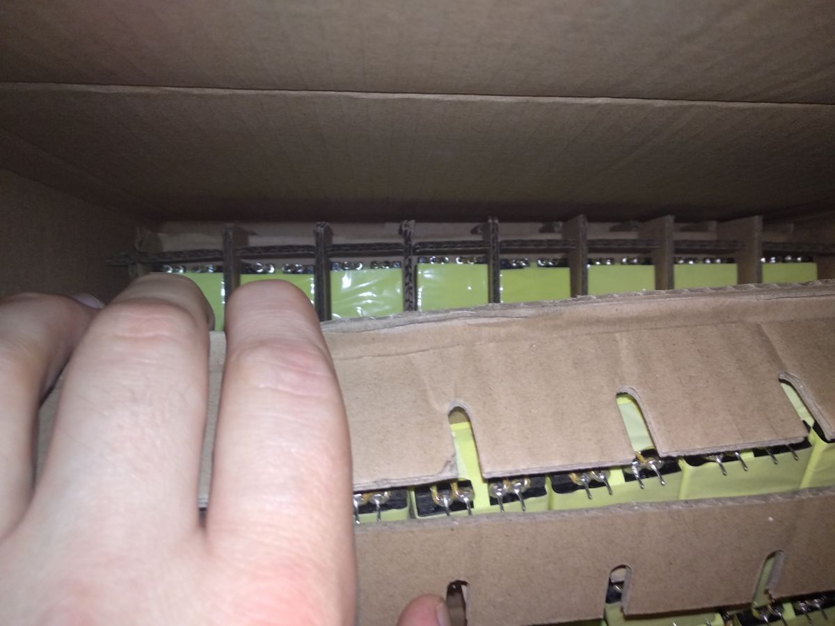
Got a ton of parts from a closed product lineup, including those flyback transformers, loads of electrolytics, diodes and inductors.
I could make a small production line with this.

Originally I intended to use primary side voltage regulation, I did browse through some designs.
Well, I found that the typical 1-2 pin resistor (mentioned in documentation for UC384x) rather "redundant" in testing.
Even when it was in operation, it remained fine with just the capacitor compensation.
It runs just on fixed current alone, reaching the set maximum inductor current. There is no other regulation at work here.
Decreasing R2 increases the output voltage a lot. If the voltage feedback was limiting, then the thing wouldn't budge.
The divider on feedback pin of UC3845 is set to keep the voltage at 20V.
This particular mosfet can take 30V on gate.
Most of the time the voltage is only around 12-13V or so, because of R10+R11.
I have encountered the problem of high auxilary voltage when toying around and it remained like that.
As for regulation, tubes don't really need regulation that much.
Tubes can take well over 500V in a cold state and the second grid can have extra filtration that makes the output pentode quite resistant to ripple.
In this particular case the circuit turns on, HV goes up to around 300V (only the filament is loading down the circuit) and then once the tube heats up it goes down to 185V.
Regulated filament current would be nice, since a series resistor (would be working as a shunt) is required anyway, otherwise reaching high enough HV wouldn't be possible.
If I were to set the heater voltage just right (no series resistor with filaments), then the HV would be around the 140-150V mark, which is a little too low (works for some tubes though, like EL82/6P18P).
Ideal would be U-type tubes, operating heaters at 100mA current. Those however are rather rare, though UCL82 (same as PCL82) does exist.
Will do a brand new PCB, this time with everything on a single board, 431 filament current regulation and LC filter for HV.
An extra thing to consider, is that this thing, with HV only and some regulation would be a very small isolation transformer for powering stuff like switching power supplies that can run off DC.
And technically speaking, this is a step down design, since the mains are 230V, the primary DC side is over 300V.
I do have some experience with powering tubes directly from mains (RF stuff), however I really wanted to try and make a proper supply, that could replace the expensive mains transformer.
That was the main idea here. If I can make a compact, inexpensive supply that can get around the "audiophile tax" so to speak (transformers "dedicated" for tubes are rather expensive, yet I can get a brand new "non tube" transformer for less than half the price).
One question to ask (since I'm just a self learning amateur), why is the snubber design, as shown in my schematic, not really that common ?
I did a lot of testing and couldn't bring down the overshoot using the "traditional" design.
Then I looked through some materials on snubber design and found this thing
https://rudys.typepad.com/files/snubber-e-book-complete.pdfFigure 4-45 page 123
I rewired the thing and was amazed at how good it works.
C4 sits at around 400-450V and slowly discharges into the main tank capacitor through R8.
Also some extra notes.
For a normal amplifier that uses 6.3V filament tubes, a half-bridge is a lot better design.
First of all, voltage multipliers can be used, which makes HV a lot easier to obtain.
Then you don't need any regulation at all. An IRS2166 can be used to make a current limited PSU with APFC.
IR2153 works fine too (except for the absent current limit part), it's my second design, that I'm going to use for a bigger amp.