Author Topic: controlling a robotic arm (Grad proj )  (Read 8187 times)

0 Members and 1 Guest are viewing this topic.

Offline ahesTopic starter

  • Contributor
  • Posts: 21
  • Country: eg
controlling a robotic arm (Grad proj )
« on: January 20, 2012, 10:11:29 pm »
Hi.

I'm a senior in control department of an engineering faculty and my graduation project is an industrial robotic arm.

actually this isn't my first time, I made this project 3 times before ( the results came up bad ) the last one was the only one worked automatically.

here is a video for this last robot arm:


And yes I know it's slow and the path trajectory isn't uniform.

that is what I want to improve in this grad project

for the speed problem this was something wrong with the motors driver, and I'm planning to use inverse kinematics technique to solve the trajectory problem.

I'm writing this topic because I was planning to make tutorials and videos about the phases that my grad proj will go through. and I was planning to make them in Arabic.

and I saw Dave's videos on youtube (they helped me alot ), and it encouraged me to make an English version of it too. and the best place for that is this forum.

any suggestions, help or any comment is appreciated.
 

Offline ahesTopic starter

  • Contributor
  • Posts: 21
  • Country: eg
Re: controlling a robotic arm (Grad proj )
« Reply #1 on: January 20, 2012, 10:44:34 pm »
I will start trying to solve to speed problem.

In the attachments you will see the schematic and the layout of the old driver that I used.
If you want to increase the speed of a stepper motor you have to work on a higher voltages ( that means you will charge the coil of the motor faster, delivering the required amount of mechanical power of the new speed, ext ) I will get back to this later in the designing step of the new driver.

fair enough, what I suffered from really when I was designing the old stepper motor driver is if I want to change the driver parameters, like ( changing the chopper frequency for the chopper regulator, the rotating speed ) I had to change the values of the RC oscillator and it was really hard

you have to make you chopper frequency at least 10 times faster than your rotating speed and stuff like that ( don't worry I will get them in details later ) my point is it will be much better if you made all of these parameter changeable from digital device.

that's why I decided to design a kit for developing the stepper motor driver.

I'm using mcu AVR atmega8 that will receive command from a custom GUI ( I programmed that GUI using Ms VB6 ) those commands are the parameters that I want them to be changeable like the speed, direction, chopping frequency or even enabling or disabling the whole driver.

long story short is I made this circuit ( you can see the schematic in the attachments too) and It actually succeeded but after leaving it for couple of weeks I tried to program it again but the mcu on the board  is responding with pullshit I don't know where is the problem but I'm trying to fix it and I will keep you up to date.


Offline amspire

  • Super Contributor
  • ***
  • Posts: 3802
  • Country: au
Re: controlling a robotic arm (Grad proj )
« Reply #2 on: January 20, 2012, 10:52:18 pm »
I am impressed just to see how far you have got. It may be early stages, but the arm is on the way.

If you are going to use inverse kinematics, what sort of coordinate system are you using? A cartesian system, or some sort of quadrature system?

I suspect that if you are going to use IK, the Atmega8 will struggle, as you will need a fair bit of matrix and trig processing power. Something with a floating point hardware would be good.

One of the things you could do is to use an animation program to model the arm, and to generate smooth trajectory paths. That would be a quick way to get some really smooth arm motions that are changing all axes simultaneously, and even with the current motor speed, it will make the arm much faster.

Please make some tutorials. They should be interesting.

Richard.
 

Offline Rerouter

  • Super Contributor
  • ***
  • Posts: 4695
  • Country: au
  • Question Everything... Except This Statement
Re: controlling a robotic arm (Grad proj )
« Reply #3 on: January 20, 2012, 11:13:20 pm »
just a small thing, it looked as if the arm was hunting (rotation wise) as it lowered to each can, is there any specific reason behind this, or was it just the rotation of the lowering motor?
 

Offline ahesTopic starter

  • Contributor
  • Posts: 21
  • Country: eg
Re: controlling a robotic arm (Grad proj )
« Reply #4 on: January 20, 2012, 11:34:14 pm »
@amspire

the coordinate system I'm going to use will depend on the type of joint for each link

the arm I'm going to use has 3 revolute joints "rotating around a fixed axis " so I'm going to use a cylindrical coordinate system for each link and then all of them will be converted into a Cartesian coordinate system originated at the base, and this c-s will be the reference that all of the other points (the gripper, and all the work pieces ) is measured with respect to this system.

ATmega8 is used just for the kit it's not the main processor in the system.
Remember that the PC is involved, it will send the path as a punch of points in a matrix like a G-code in a CNC machine.

and the processor will solve the unknown parameters using iterative techniques.

if Atmega128 isn't enough I can upgrade to ARM core based mcu.

for the floating point and trigonometric function it will depend on the sampling speed of the controller, still early to talk about this stage yet.

@Rerouter

do you mean the vibration.
 

Offline mobbarley

  • Regular Contributor
  • *
  • Posts: 200
  • Country: au
Re: controlling a robotic arm (Grad proj )
« Reply #5 on: January 21, 2012, 12:05:01 am »
Did you program acceleration / deceleration into it? It appeared to start and stop pretty harshly.
 

Offline ahesTopic starter

  • Contributor
  • Posts: 21
  • Country: eg
Re: controlling a robotic arm (Grad proj )
« Reply #6 on: January 21, 2012, 12:13:37 am »
No,

I had to deliver this arm in a harry, but if I did I would've been able to use IK.

but I have an idea for the motors to accelerate and decelerate according to specific function

like making the motor speed to follow a sinusoidal wave form, this is useful if you want to move the arm in circle for example.

but every thing in time, the first thing I've to do is to make a decent driver.
 

Offline mobbarley

  • Regular Contributor
  • *
  • Posts: 200
  • Country: au
Re: controlling a robotic arm (Grad proj )
« Reply #7 on: January 21, 2012, 12:25:32 am »
driver for steppers? I've used this board in the past - the IC is easy to work with.

http://www.schmalzhaus.com/EasyDriver/index.html
 

Offline ahesTopic starter

  • Contributor
  • Posts: 21
  • Country: eg
Re: controlling a robotic arm (Grad proj )
« Reply #8 on: January 21, 2012, 12:49:22 am »
Thanks for the link

but I've read the specs and it said that the driver is working on 750 mA per pahse, but one of my motors is sucking 6 A per phase and this enough to blow up the circuit.
alse I'm planning to use 80v supply and the circuit can take only 30v max.

I think I will go through designing my own driver and it would be nice having a design that takes the parameters I'm putting for my robot, it can replace the commercial ones in our little projects.
 

Offline mobbarley

  • Regular Contributor
  • *
  • Posts: 200
  • Country: au
Re: controlling a robotic arm (Grad proj )
« Reply #9 on: January 21, 2012, 02:39:46 am »
Absolutely - for that kind of power level you won't get an integrated IC,  mosfet bridges in a package could still be used to save space compared to a completely discreet design.
 

Offline ahesTopic starter

  • Contributor
  • Posts: 21
  • Country: eg
Re: controlling a robotic arm (Grad proj )
« Reply #10 on: January 21, 2012, 03:28:55 am »
I used before 3A mosfet bridge, It wasn't cheap 30 EGP about 6$ us.

Size isn't really my biggest concern, I'm going with discrete components.

the problem is how to drive them at higher frequencies, they have quite big input capacitance and if you didn't drive them strongly, you might be ended up operating in the linear mode.

do you remember the video Dave made about designing Lab power supply when he used a transistor to switch off the linear regulator in the current limiting mode.

the same thing will happen in here, at higher frequencies the input capacitance will filter the switching signal to an average dc voltage and that will drive the transistor in the linear region.

so that I need a high output current capacity transistor driver, that can work on higher voltages.

I found IR2110 MOSFET driver and it can operate to 500 V, and I will test it later.
 

Offline mobbarley

  • Regular Contributor
  • *
  • Posts: 200
  • Country: au
Re: controlling a robotic arm (Grad proj )
« Reply #11 on: January 21, 2012, 06:57:33 am »
Mosfet driver ICs - but i'm sure you already know that as you know about gate capacitance.


Offline daedalus

  • Regular Contributor
  • *
  • Posts: 140
  • Country: gb
Re: controlling a robotic arm (Grad proj )
« Reply #12 on: January 23, 2012, 02:45:46 pm »
ahes: neat arm, and for a graduate project it looks like you have put a fair amount of effort in already. Here are a couple of things I would do:

Buy and fit an E-STOP! seriously you have what look like pretty high gear ratios on this thing, and although its slow now, im sure you will turn the speed up at some point. Im sure there are some pinch hazards on the thing, and its a good habit to get into, especially on prototype robots which tend to go wrong a fair bit.

Maybe redesign the gripper a bit. At the moment you have a rigid mechanism with stiff jaws, and no sensing of contact pressure. This means that you are relying on compliance in the object you are grasping to ensure sufficient force is achieved during movement (and in the process crushing the can a bit).
Either taking a serial elastic actuator approach on the motor (spring in series with motor drive, sensing of spring position), or changing the gripper teeth to a compliant material like rubber, and measuring contact force with an FSR. The latter approach could probably be retrofitted easily enough, and is similar to how the PR2 gripper works.

Control wise it seems like you are doing bang bang control on the axes. Having a trapezoidal velocity profile will smooth things out a bit. With regards to path planning, take a look at http://www.kuka-robotics.com/en/products/software/educational_framework/arm_tutorials/PS_Content_Arm1.htm which covers the basics of generating paths for arm controllers. As long as your low level control is embedded, you can build the fancy stuff (FK, IK, path generation) as PC software and just command the arm over a serial bus, you don't have to worry about getting it all banged out on a cheap micro.

Good luck with your project.


Offline ahesTopic starter

  • Contributor
  • Posts: 21
  • Country: eg
Re: controlling a robotic arm (Grad proj )
« Reply #13 on: January 23, 2012, 10:53:11 pm »
Quote
neat arm, and for a graduate project it looks like you have put a fair amount of effort in already.
just I wanna clarify something, the arm in the video isn't my graduation project, it's an old project
It was a job assigned to me from a factory who wanted to make something to put it in quality control gallery.

my grad proj is a new arm ( I aim to be better than the one in the video ) every time you gain some experience  8)

I have a picture for the new arm I just don't remember where at the moment, but I will post it here soon.

Quote
Buy and fit an E-STOP! seriously you have what look like pretty high gear ratios on this thing, and although its slow now, im sure you will turn the speed up at some point. Im sure there are some pinch hazards on the thing, and its a good habit to get into, especially on prototype robots which tend to go wrong a fair bit.
it hit me on my head once, but here in Egypt we don't care about safety, we have more people than  we need. It is ok if it killed some one "I'm just kidding  :D".
certainly I'll do that.

Quote
Maybe redesign the gripper a bit. At the moment you have a rigid mechanism with stiff jaws, and no sensing of contact pressure. This means that you are relying on compliance in the object you are grasping to ensure sufficient force is achieved during movement (and in the process crushing the can a bit).
yeah, that was a design error, I was interested more in the motion profile, but I already looked into some force sensors, and I'm going to use one.

Quote
Either taking a serial elastic actuator approach on the motor (spring in series with motor drive, sensing of spring position), or changing the gripper teeth to a compliant material like rubber, and measuring contact force with an FSR. The latter approach could probably be retrofitted easily enough, and is similar to how the PR2 gripper works.
I couldn't agree more.
and specially the rubber idea, I'm gonna use it if I ran out of time.

Quote
take a look at http://www.kuka-robotics.com/en/products/software/educational_framework/arm_tutorials/PS_Content_Arm1.htm
This specially what I wanted to thank you for.

the inverse kinematics and the path trajectory finding was consuming me,that I didn't have much thoughts about how to make them all move together "the joints I mean" so that each link will reach it's final position at the same time, accelerating and decelerating simultaneously.

Quote
As long as your low level control is embedded, you can build the fancy stuff (FK, IK, path generation) as PC software and just command the arm over a serial bus, you don't have to worry about getting it all banged out on a cheap micro.
yes, that's what I'm planning to do.
I want to send the path trajectory as a series of points and the MCU has only to connect the dots and filling the spaces, no IK for the MCU unit.

thanks daedalus your post really helped me a lot.
« Last Edit: January 23, 2012, 11:00:13 pm by ahes »
 

Offline ahesTopic starter

  • Contributor
  • Posts: 21
  • Country: eg
Re: controlling a robotic arm (Grad proj )
« Reply #14 on: January 23, 2012, 11:07:51 pm »
this is our new arm
just remove the link in the middle.
 

Offline ahesTopic starter

  • Contributor
  • Posts: 21
  • Country: eg
Re: controlling a robotic arm (Grad proj )
« Reply #15 on: February 22, 2012, 08:18:07 am »
sorry for being late.

The thing is I want to start with making the stepper driver and all of the control and electronics circuit.

but there were an uprising and turmoil in tahreer square where the electronics market is located, and the whole market were blocked, that why I had to wait.

but then I started making the software first, and finally I made a 3d simulator for the arm

this video will explain every thing.


any comments or other ideas will be appreciated 
 

Offline IanB

  • Super Contributor
  • ***
  • Posts: 12145
  • Country: us
Re: controlling a robotic arm (Grad proj )
« Reply #16 on: February 22, 2012, 08:57:35 am »
If you take a look at the Dymola modeling system from Dassault Systemes (there is a free demo to download) there is an industrial robot arm included as one of the demos. This is a model of a six axis arm with electrical and mechanical systems and a path planning controller. You may find some useful insights in that model.
 

Offline ahesTopic starter

  • Contributor
  • Posts: 21
  • Country: eg
Re: controlling a robotic arm (Grad proj )
« Reply #17 on: February 22, 2012, 03:15:47 pm »
It's a powerful tool, but it seems a little bit hard to use

do you have a video for path planning controller
 

Offline ahesTopic starter

  • Contributor
  • Posts: 21
  • Country: eg
Re: controlling a robotic arm (Grad proj )
« Reply #18 on: February 22, 2012, 04:25:22 pm »
take a look at this video


in robowave they made an offline programmer for the robot

you see the little arrows specifying the paths of the robot's end effector

I want to build a software that enables the user to draw this paths "like routs on a pcb" then he can put what ever he/she wants "robot commands" on those paths.

and then if you're sure that every thing is good, then you can compile the motion plane into an executable file to download it on the real robot.
 
what do you think about this way of programming.
« Last Edit: February 22, 2012, 04:28:24 pm by ahes »
 

Offline ahesTopic starter

  • Contributor
  • Posts: 21
  • Country: eg
Re: controlling a robotic arm (Grad proj )
« Reply #19 on: February 24, 2012, 04:30:36 pm »
Hello Again.

in the last video you saw when I want to change the camera view point in order to look at the robot from another place I had to move location along with each individual axis.

This was ugly and unprofessional, in all programs they rotate the camera using the mouse wheel button, and the mouse pointer location.

but there is a problem arises in here that the mouse moves in two coordinate plane and the camera is placed in a 3 coordinate system, this what we are goint to talk about here. but first we need to establish some rules.

This is not a tutorial explaing how to use directx we'll use it to ilustrate things up, using it as a tool studing it is beyond the scope of this script.
The same thing is applied on the programming language I'm using here, you can apply it on any programming language ( but if you don't know any language it is really a shame.)
The videos are going to be without any commentary this time. ( I've listened to video I made last time and my accent sounded outfall  :-\ , although it kinda sounded nice when I was hearing the words straight from my mouse  :-*)

before you continue with me you should've studied linear algebra ( specifically Matrices )

and lastly  take a look at:

http://en.wikipedia.org/wiki/Rotation_matrix

http://www.fastgraph.com/makegames/3drotation/

this is about rotating objects in space.

now to answer the previous question how to use 2 coordinate sytem to control 3 coordinated sytem.

direct x uses transformation matrices in order to manipulate every thing in the 3d world

I will asume that you've read the previous links about transformation matrix.

the first matrix that direct x uses is "the world matrix" this one represent the base coordinate sytem where every thing is placed with respect to. If this matrix is "I" ( identity matrix ) every thing will be rendered (drawed ) without altering its position or it's orientation "compounded pose"

the other matrix will represent the camera ( or your eye ) this matrix holds information about the camera postion and orientation " where the camera is looking, witch way is up, so not to draw every thing fliped upside down )

and what directx does actualy is that it will multiply those two matrices to generate one matrix that directx will use to draw every thing with respect to it.


but first it has to reverse what ever this matrix tells you

for example if you're holding a camera taking a photo of a car
if you maved the camera right then you can imagine that the car is moved left.


you see the car is moved left or the camera is moving right


it's now obvious to manipulate the camera matrix to change the way you look at the scene.

back to our problem how to use 2 coordinate mouse to control 3 coordinate camera matrix

one of the solutions "I'm using now" is to rotate around y "yaw rotation" using the mouse movement on x Axis.


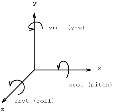
each step positive you can rotate like 5 degrees clockwise or more depending on the speed you want.


but this will leave us with 2 other axis ( x,z) and only one mouse axis to control them.

if you assigned this direction of mouse to control for example the x axis of the world "graphics world, not the world we live  ::) "
you will get the results in the next video


After couple of rotations and you'll be lost then you will foget how to go back to the orginal pose.

the solution for this particular prblom is not to rotate around the the world's X axis, use the camera X axis instead, now you will gain control over the world's X,Z axis.
the axis of rotation depends on the order of rotation matrix multiplication.

if you pre-multiplied the camera matrix by the rotation matrix ( C * R ) then you will get a rotation around the camera's X axis

but if you post-multiplied the camera matrix by the rotation matrix ( R * C ) then you will rotate around the World's X axis

and what we're going to do is that when we rotate around Y "yaw rotation " we will Post-multiply and in the case of x we'll pre-multiply

look at the results yourself in the next video


oops the rotation is around the x but the camera is filming the sky.

imagine that you're holding the camera, in the yaw rotation you can move around the object but in the  pitch case "rotaion around X" you have to evovle 2 wings and fly  ;D

in mathimatics you have to rotate the vector connects the worlds's coordinate system's origin to the camera's origin

then you have to multiply the Rotation matrix to this vector and then you will rotate that vector with the camera "fly with the camera  :-\"

here's the final result


-------------------------------------
finally: I know all of the stuff in here are not electronics but this really important in robotics "Transformation matrices I mean"
If there's any one interested of what I'm saying please let me know.
the purpose of writing this thread in here, is to share every step I'm taking as my project is evolving with people who have the same interest I do. and first I thought it's going to be a couple of chips and a software on a microcontroller then I'm done.

so please tell me should I continue.or you really guys want to stick to electronics ;D
« Last Edit: February 24, 2012, 05:44:54 pm by ahes »
 

Offline FreeThinker

  • Frequent Contributor
  • **
  • Posts: 791
  • Country: england
  • Truth through Thought
Re: controlling a robotic arm (Grad proj )
« Reply #20 on: February 24, 2012, 05:15:32 pm »
I remember my first experience with an industrial robot arm (Kuka). I can say without doubt that they are very unforgiving if you get in thier way.
Machines were mice and Men were lions once upon a time, but now that it's the opposite it's twice upon a time.
MOONDOG
 

Offline ahesTopic starter

  • Contributor
  • Posts: 21
  • Country: eg
Re: controlling a robotic arm (Grad proj )
« Reply #21 on: February 24, 2012, 05:46:34 pm »
And the last video is up.
I don't know is it me or youtube is getting slower.

Quote
I can say without doubt that they are very unforgiving if you get in thier way.
get in their how, and what they gonna do.
 

Offline daedalus

  • Regular Contributor
  • *
  • Posts: 140
  • Country: gb
Re: controlling a robotic arm (Grad proj )
« Reply #22 on: May 21, 2012, 01:17:22 pm »
Hi Ahes,

Just a quick hint, in case you are still having issues with the 3d mapping for mouse, what you are looking for is called an arcball algorithm. This projects your 2d mouse movements to rotations of a sphere, and calculates the correct transform for the object, which allows 3 rotational DoF with a 2d mouse. It will be documented in any good directx book, and I bet there are loads of tutorials online.

You will still need 2 modes, one with arcball for rotation of scene, one for panning.

The rotational effect is that the scene rotates in front of viewer, if you want a more first person effect (like your head turning left/right), you could implement a first person camera system, again there will be lots of tutorials for this.

Its probably worth looking at building a scene graph into your code, this is a tree structure where each node has its own relative matrix transform, and a list of child objects. If you google scene graph you will find lots of tutorials.


Share me

Digg  Facebook  SlashDot  Delicious  Technorati  Twitter  Google  Yahoo
Smf