Tim got it right or almost right, and a few other people were close. It could be seen that the mv/Div was set very low, 500uV/ in one shot and 5mV/ in the other, but there was no trace noise in the shots, look how noise-free the waveform is.

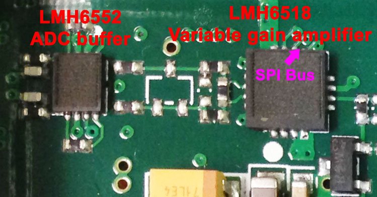
In Part 5 I said the variable bandwidth VGA in the front-end is responsible for generating most of the noise in the path. Noise-free waveforms in the screenshots with such small mv/Div could only be obtained if to bypass most of the input stage and inject the signal into the ADC buffer. It was too much problem to get the signal right into the ADC pins, it was easier to do it with the ADC buffer stage as shown in the following picture.

I unsoldered the two SMT resistors (they are two zero Ohm jumpers) located near the VGA and that gave me access to the LMH6552 ADC buffer input. hooked up a RF balun to it to convert differential input into single ended input, with a pigtail microcoax soldered to the other end of the balun.
I could then perform sweeps and do bandwidth measurements of the ADC buffer + ADC, lets take a look again what I posted in Part 5:

We are looking at the blue line which is the ADC buffer + ADC transfer function. In fact it had gain so the chart was normalized to the maximum gain point which occurred at around 300MHz with 5dB gain. Therefore if we consider the leftmost end of the blue line to be 0dB, the -3dB point to the right of it and relative to it would be around 800...850MHz (the blue line). So technically this part of the signal path is capable of 800MHz bandwidth, and that was what you saw in the screenshots with a sinewave and raise time test.
I recall doing a few sweeps and if I remember correctly the scope triggered up to 600MHz. Above that it rolled but I could stop it and see the waveform up to 800MHz (with 2GS/ sample rate, single channel mode). So basically the capability is there but is crippled by the VGA bandwidth limit. Technically the VGA SPI bus could be hacked, commands intercepted and corrected so in Full bandwidth mode it could be set to say 600MHz, so what you get is a 500MHz scope for almost no extra money. The problem however is with highjacking the VGA SPI bus tracks, doing this would require unsoldering the LMH6518 VGA and perhaps fitting it on a small PCB and retrofit that PCB back to where the VGA was. Too much trouble, though in theory can be done. May be I would have done it, had I not decided by the time I will not keep the scope. Also, I had not thoroughly tested the scope in all modes with this, beside the FFT which still worked correctly. I think the frequency counter became shaky and gave incorrect readings above 450MHz or so. Anyway, this may be an interesting info for a determined person to explore more.
So, [Dave mode] if you liked this info, give it a thumbs up, that always helps [/Dave mode]


