Author Topic: Amplified Shunt for mA, µA and nA Current Measurements  (Read 2552 times)

0 Members and 1 Guest are viewing this topic.

Offline Markus EnginethrustTopic starter

  • Contributor
  • Posts: 11
  • Country: de
Amplified Shunt for mA, µA and nA Current Measurements
« on: August 18, 2018, 12:45:40 pm »
Hi, this is a redesign of Daves opensourced µCurrent and µCurrent Gold  :-DMM


Changes:
-> Minimal PCB size (reduce cost, takes up less space on the bench)
-> Removed large switches (reduce cost)
-> Removed large gold posts (small header pins better in my use case, reduce cost)
-> Removed on-led and voltage monitor (longer battery life, i don't forget switching it off ;) )
-> Removed second precision op-amp (reduce cost)
-> Added GND-Pads for shielded case (see video for details)

If this suits your needs too, you can find the gerbers and the partlist together with a 3D-printable case on Thingiverse: https://www.thingiverse.com/thing:3055498

Video showing its operation and build: https://youtu.be/wkz311_8YzY

If you want Daves well proven original design with improved performance please buy/rebuild it instead!

I would be happy about feedback.
 

Offline JS

  • Frequent Contributor
  • **
  • Posts: 947
  • Country: ar
Re: Amplified Shunt for mA, µA and nA Current Measurements
« Reply #1 on: August 18, 2018, 03:27:49 pm »
I think you missed the point in a few things the shunt configuration for example and the low side sensing of the shunt aren't ideal. As you are using cheap terminals you could forget about the switch and use 4 output terminals, connecting the different shunts in series and selecting the one in use by connecting to the right terminals.

I do like the form factor, if I were doing something similar I think I'd add a selectable output filter.

I'm also worried by the lack of protection, as input voltage is so low, diodes shouldn't introduce much error so I would use some, with the 10k input the opamp is easy to blow otherwise. Also the 10Ω resistor is easy to blow too...

JS
If I don't know how it works, I prefer not to turn it on.
 
The following users thanked this post: Markus Enginethrust

Offline Markus EnginethrustTopic starter

  • Contributor
  • Posts: 11
  • Country: de
Re: Amplified Shunt for mA, µA and nA Current Measurements
« Reply #2 on: August 18, 2018, 05:33:39 pm »
Iteresting points!

As long someone uses the tool with a weak low voltage supply (or a current limited low voltage supply) overvoltage and current limiting protection is not needed, but i agree a fool proof device is nice and you never know when you need it!
For overvoltage protection one would put a zener parallel to the 10k Resistor. The maximum voltage across the shunts when measuring is approx. 13mV. I have no idea how large the reverse current of a zener diode is, at such a small voltage, but we want to measure nA, so it has to be very small. As far as i know at 1V zener-Diodes typically already have reverse currents in the µA range.

For saving the small resistors from to much current one would have to connect bigger current limiting resistors in series, this additional load would alter the measurements by increasing the low potential of the load and is therefore not desirable, or do you know a better way? The used resistors are not very expensive, i am fine with having them as fuses  :D

It did not occur to me to use the tool on the high side of the load, i tested it and you are right it only works well on the low side. It still kind of works but the signal is very noisy. Using an amp with a differential measurement of the shunt voltage should make this kind of measurement possible, right?
 

Offline Gyro

  • Super Contributor
  • ***
  • Posts: 9746
  • Country: gb
Re: Amplified Shunt for mA, µA and nA Current Measurements
« Reply #3 on: August 18, 2018, 06:12:30 pm »
I'm not sure I would have gone in the same direction, I would have gone for addressing the uCurrent's weaknesses, although I can see that making it cheaper has its attractions too. The weaknesses of the original are:

1. Not enough current shunts - trying to get away with one shunt for every 3 decades is a serious flaw, leading to 'excessive' (ie. higher than it needs to be) voltage burden or poor resolution on currents that fall in between these decades. Also leading to...

2. Excessive gain. Skimping on shunts means that you need to add more gain than is needed, with the associated compromises a x100 gain amp using an auto-zero opamp (frequency response, noise and stability). With appropriate shunts, you wouldn't need more than x10, easily achievable with a normal low Vos opamp with better performance. There's a possible trade-off there between opamp cost and shunt resistor cost.

3. No input protection - you can kill the opamp in less than a second with careless connection on the nA / uA ranges. I noticed that you removed the series resistor on the opamp, ok it was too low in value to provide any real protection but you could have changed that to a more sensible value. I would advise a pair of inverse parallel diodes across the input for proper protection though - it's not difficult to find diodes that leak no more than a few pA with 10mV across them.

Switching the input terminals to headers is an matter of choice it might be convenient for jumper leads, but of course not 4mm ones. I think the uCurrent ones are Chinese speaker terminals which seem too big and un-insulated but are cheap. I might be tempted to find a compromise between the two.


I guess you are achieving your goal of a 'cheap' version - there's no reason for you not to address the input protection issue though.  :-\


Edit: Thinking aloud, a simple way of achieving the correct number of shunt resistors (one per decade) using your header pins for range selection rather than a PCB switch. current values shown are for 10mV burden, so x10 amp would give you 100mV. It's just a quick sketch to show the idea, the gain would need trimming.  Also note that the opamp would see 11k worst case source resistance so would need to be CMOS. As I say, just thinking aloud.
« Last Edit: August 18, 2018, 07:23:26 pm by Gyro »
Best Regards, Chris
 
The following users thanked this post: Markus Enginethrust

Offline Markus EnginethrustTopic starter

  • Contributor
  • Posts: 11
  • Country: de
Re: Amplified Shunt for mA, µA and nA Current Measurements
« Reply #4 on: August 19, 2018, 12:14:39 pm »
Thanks for the replies, this was exactly what i was looking for.
I will keep your improvements in mind for the next designs or new redesign. Cheers!
 

Offline Markus EnginethrustTopic starter

  • Contributor
  • Posts: 11
  • Country: de
Re: Amplified Shunt for mA, µA and nA Current Measurements
« Reply #5 on: September 10, 2018, 11:08:54 am »
I had to use this tool and was not able to do so satisfingly because of a lack of shunts.

Sooo... i redesigned this thing agian and tried to improve the performance.
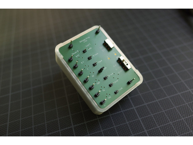


Changes:
* As suggested there is now one shunt for each decade
* New amplifier OPA388 has a higher bandwith than the old op-amp while having similar charateristics otherwise except higher current draw
* 3xAAA Batteries as voltage source -> No additional noisy IC's necessary to provide another voltage level (see video)
* Negative output range as before (0V to -1.5V) but positive output range is doubled (0V to 3V) with new batteries
* Small resistors for low noise
* As suggested selectable capacitive input filters have been added
* No other capacities needed since there is virtually no noise

Video showing use and build:

Gerbers, Partslist, Case: https://www.thingiverse.com/thing:3092910

Why not only gain of x10 instead of x100?
The main difference would be needing the x10 amount of voltage to get the same output voltage. E.g. to get 3V on the oscillosope one would need to have 0.3V over the shunt. This is quite ecessive when having a low voltage circuit. To make matters worse it is easier to get to much voltage on the op-amp input when feeding it with higher voltages.
(Also x10 bigger resitors are needed for the same input range, which induce more noise which is especially annoying when measuring small currents.)

Why no overvoltage protection?
I looked into it and simulated some diodes. But with the suggested inverse diode solution i always get >1nA current draw at 0.03V (maximum voltage accross the shunts). Problematic is the forward diode. But with a bit of care nothing should happen with the circuit since the operating voltages are so much smaller than the maximum allowed voltage on the input (approx. 3V). And in case somthing brakes it is easy to repair because of its simple design.
 

Offline Kleinstein

  • Super Contributor
  • ***
  • Posts: 14483
  • Country: de
Re: Amplified Shunt for mA, µA and nA Current Measurements
« Reply #6 on: September 10, 2018, 04:25:50 pm »
For just low frequency operation a single x 100 stage is usually OK. It is only with higher frequencies (e.g. > 10 kHz) that the 2 stage design is needed.

The noise from the virtual ground is not relevant, it only effects the common mode signal and would not be visible at the output. The idea here would be more like using a lower power OP. Another option would be to have the virtual ground moving the opposite way of the output. This way the output range could get larger (e.g. +-4 V with a 4.5 V supply).

The current range switching version is a little odd and not the best solution for the smaller shunts: the switch (jumper) resistance is included in the measurement.  This could be an issue for the 1 Ohms shunt. The old version with 2 separate switches for voltage and current was more accurate. With 100 Ohms an higher one can probably get away with just 1 switch.

Some protection would be a really good idea. A possible way to reduce diode leakage is to have 2 diodes in series and feed the approximate voltage back to the middle of the diodes, so that one pair of diodes only sees a very small voltage (e.g. 5 mV range). The down side it that protection would be with about 1.4-2 V peak, so that some of the smaller shunts could still suffer from high power. Having a little higher power for the 1 and 10 Ohms shunt might be a good idea anyway, to limit self heating effects.

An alternative would be to separate the small currents (e.g. < 10 µA FS) to a separate amplifier, e.g. build as an trans-impedance amplifier.
 

Offline Markus EnginethrustTopic starter

  • Contributor
  • Posts: 11
  • Country: de
Re: Amplified Shunt for mA, µA and nA Current Measurements
« Reply #7 on: September 11, 2018, 07:53:59 am »
Quote
the switch (jumper) resistance is included in the measurement.  This could be an issue for the 1 Ohms shunt.
I think this is a misunderstanding, the jumper-resistance is in series with the large input resistance of the op-amp -> Nearly no voltage is dropped there, otherwise the small shunts (especially the 0.01 Ohm one) would not work at all.

Quote
The noise from the virtual ground is not relevant, it only effects the common mode signal and would not be visible at the output.
I thought that as well, but in the first version the op-amp output was very nosy without its capacitors C1 and C2, i am suspecting some transient effects occur when its ground potential changes fast through noise? Now no capacitors are needed for the power supply.

Quote
A possible way to reduce diode leakage is to have 2 diodes in series and feed the approximate voltage back to the middle of the diodes, so that one pair of diodes only sees a very small voltage (e.g. 5 mV range).
As i understand it, you would use the same idea as Gyro in the post before but use multiple diodes in series to have a smaller voltage drop across each of them? I like that. This could work. I think i am happy for now but if i redesign i would look into that.
 

Offline alex-sh

  • Regular Contributor
  • *
  • Posts: 179
Re: Amplified Shunt for mA, µA and nA Current Measurements
« Reply #8 on: June 09, 2019, 12:42:46 pm »
Did you complete this project?
From my point of view, you have not addressed the main disadvantage of the uCurrent - inability to measure a sleeping AND waking up current of the MCU, ie autoranging
This is a must feature designing sensors and perhaps not very useful for anything else.


Share me

Digg  Facebook  SlashDot  Delicious  Technorati  Twitter  Google  Yahoo
Smf