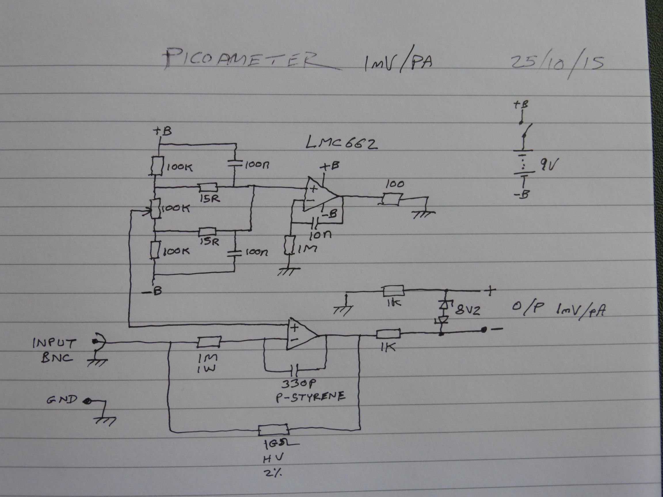
I've finally got around to putting my own Picoammeter together. It uses the LMC662 as previously discussed.It seems to work pretty well and readings seem to be stable and repeatable. Maximum current is around +/-4.5nA, that will drop to +/-2.5nA at battery end of life voltage, assuming that I risk leaving it in there that long. Supply current is just under 1mA, even adding the most frugal of power LEDs would double this, so I haven't bothered.
Accuracy seems to be fine - within the limits of my test capability anyway. Tested with my only 10G ohm resistor (also 2%) it reads 1.022nA at 10V, close enough. Input voltage offset is less than 60uV using a randomly chosen LMC662.
EDIT: Ignore the 60uV, that was due to me not having nulled the Vos properly the other day.


I've included a protection resistor within the feedback loop which should be good to +/-500V on the input, that's with 0.5mA through the LMC662 protection diodes (spec limit 5mA) so in practice is limited by the breakdown voltage of the resistor (I used a 1M large bodied carbon film).
I've also included a null adjustment pot for the op-amp offset voltage (range approx 1.35mV). I've successfully nulled it to 1uV on my bench DVM but in practice it's ridiculously sensitive to external influences at that (fA) level. The LMC662 Vos also drifts over the supply voltage range by a few 10s of uV, so in practice it's fine for zeroing at the 100fA level (see pic). Vos TC is only 2uV/'C so not an issue.
I've included rudimentary output protection, the two 1k resistors are to ensure stability against capacitive loads (oscillation shows up as a few mV of offset).

Construction is my favorite double sided Manhattan style, using single sided copperclad. The input circuit air-wired and parts cleaned with IPA (it took several hours to stabilize afterwards - mainly the polystyrene cap I think).
