Author Topic: Need help with a PFC controller  (Read 2814 times)

0 Members and 2 Guests are viewing this topic.

Offline JolleTopic starter

  • Contributor
  • Posts: 25
  • Country: dk
Need help with a PFC controller
« on: May 09, 2012, 10:17:05 am »
Hi
I am designing a 120W PFC using a Texas instument UCC28051 controller. The converter works as it should when I look at the output voltage, which is about 396 V, but when I look at the current through the inductor it looks like the controller enters some kind of burst mode?!

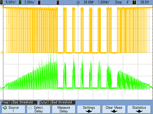
You can see a plot of the inductor current (green) and gate signal (yellow) below, during a 50 Hz cycle, the converter was delivering 60 watt to a load when the plot was made:


Has anyone seen a PFC behave this way before and know why it behaves as it does?

Regards
 

Offline muvideo

  • Frequent Contributor
  • **
  • Posts: 418
  • Country: it
Re: Need help with a PFC controller
« Reply #1 on: May 09, 2012, 10:57:51 am »
I would check these:
- core saturation (linear voltage ramp on CS pin)
- spikes on CS pin
- device supply voltage Vcc
- ZCD pin

Does the output voltage fall or is regulated?

Fabio.
Fabio Eboli.
 

Offline Kremmen

  • Super Contributor
  • ***
  • Posts: 1289
  • Country: fi
Re: Need help with a PFC controller
« Reply #2 on: May 09, 2012, 11:13:54 am »
But isn't it supposed to behave something like that? A PFC is doing 2 things: maximize cos(phi) i.e. make voltage and current equal in phase, and secondly minimize current spiking due to capacitive load. The ideal would be a resistance-like V/I curve. The PFC cannot do anything to the instantaneous line voltage but by modulating it can distribute the current more evenly over the half-wave.
Just by looking at the picture i cannot say if that is what it is doing, or if it is some fault condition.
Nothing sings like a kilovolt.
Dr W. Bishop
 

Offline muvideo

  • Frequent Contributor
  • **
  • Posts: 418
  • Country: it
Re: Need help with a PFC controller
« Reply #3 on: May 09, 2012, 11:34:05 am »
But isn't it supposed to behave something like that? A PFC is doing 2 things: maximize cos(phi) i.e. make voltage and

As far as I know to do so that current envelope should be like a sinusoid semiperiod,
the control loop then changes (acts on time scales slower than a semiperiod) 
the current value to regulate the output voltage on the capacitor bank. 

Fabio.
Fabio Eboli.
 

Offline Kremmen

  • Super Contributor
  • ***
  • Posts: 1289
  • Country: fi
Re: Need help with a PFC controller
« Reply #4 on: May 09, 2012, 11:39:34 am »
Well yes, but i am not familiar with that chip and its capabilities. In case it just does a rough approximation this could be the result. Or then it is just malfunctioning.
Nothing sings like a kilovolt.
Dr W. Bishop
 

Offline JolleTopic starter

  • Contributor
  • Posts: 25
  • Country: dk
Re: Need help with a PFC controller
« Reply #5 on: May 09, 2012, 01:36:31 pm »
Kremmen hit the nail on the head with the comment about my IC being malfunctioning. I hadn't thought of that since the controller was regulating, but when I soldered on a new IC everything worked fine and my PF is now very close to 1  :D

So thanks to all of you who helped me with my relative simple problem.


Share me

Digg  Facebook  SlashDot  Delicious  Technorati  Twitter  Google  Yahoo
Smf