I put the soldering iron away this afternoon and made a start at documenting this discrete-transistor Pong MkII. This is mostly because the circuits were part scribbled on multiple sheets of paper and part in my head. By alternating between soldering and documenting the design I have less chance of getting lost.
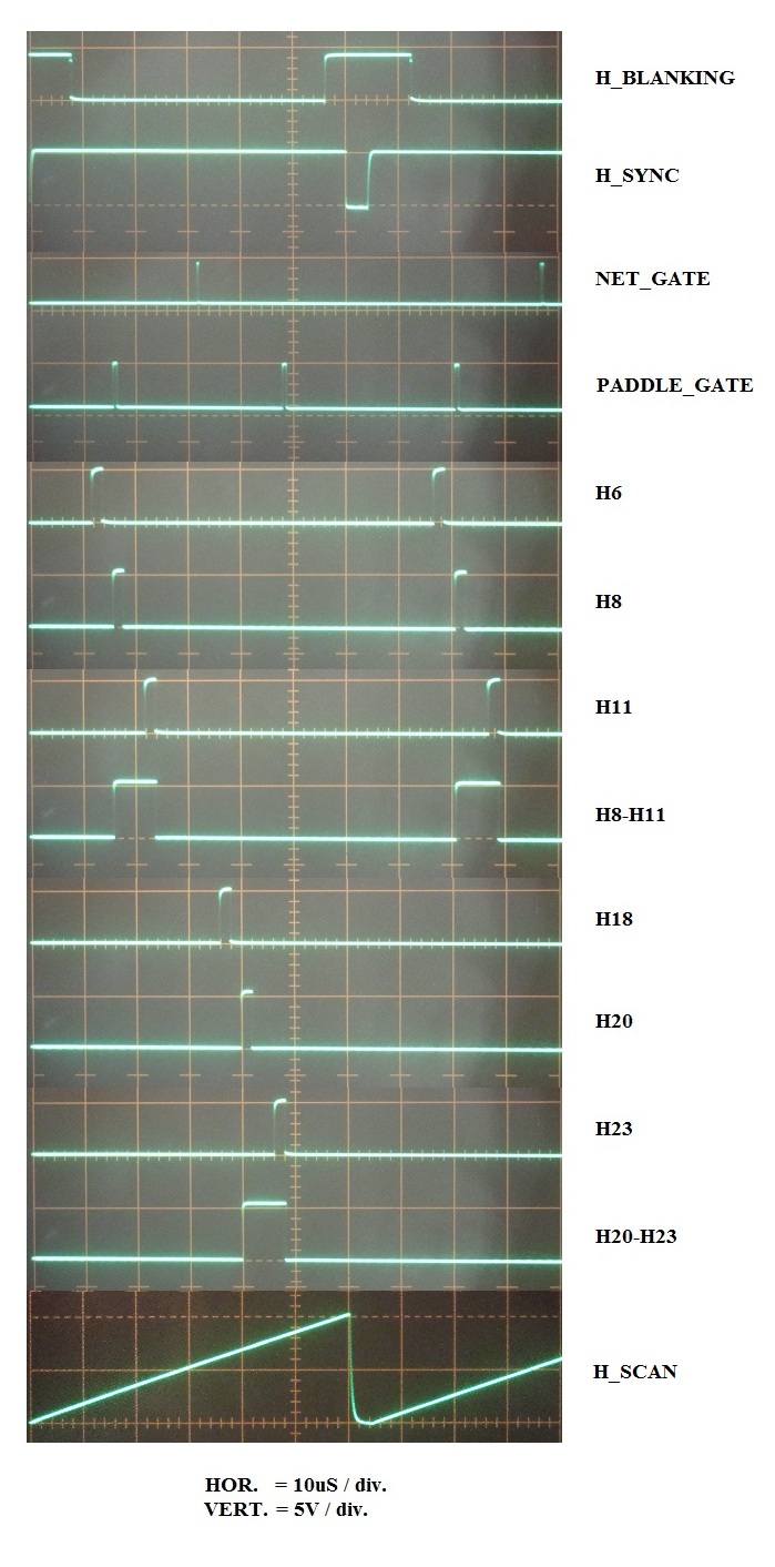
Here are complete details of the horizontal timing and video generator board. A master LC oscillator of 500 kHz clocks a 5-bit binary ripple counter made up of cascaded toggle flip-flops.
The necessary video signals are simply decoded by (N)AND gates. Some trickery was required here however as this method of decoding a ripple counter is prone to glitches in the decoded outputs as the clock state ripples through the binary counter due to the propagation delays of the flip-flops. Glitches on the decoded outputs are not acceptable here as the video signals are being generated live as each horizontal line is being scribed on the display screen.
I solved this problem by designing the flip-flops of the ripple counter to be quite fast (using MPSH10 transistors) and conversely designing and (N)AND gates for decoding to be only adequately fast for the application, rather than excessively so, such that the decoders are too slow, by a comfortable margin, to respond to and pass through the erroneous binary states of the counter during the ripple-through of the clock.
The DTL (diode-transistor-logic) N(AND) gates are made "slow" by using comparatively-lowly BC550C transistors with a relatively weak base pull-up. The AND gates that provide the horizontal video signals for generating the scoreboard display digit segments are comprised of a BC550C NAND followed by an MPSH10 DTL inverter. The through-put propagation delay of this combo is a clean and stable ~120nS and the MPSH10 inverter provides (in addition to the required polarity inversion) a squared-up output with fast rise and fall times.
The MSB (HR16) of the horizontal ripple counter is at the line frequency (15,625 kHz) and it is used as the clock source for the vertical line counter. The horizontal video component of the paddles and the court net are approximately 600nS wide and 300nS wide respectively. As this is substantially less than the 2uS master clock period, these video signals are produced by triggering high-speed monostables.
All of the signal outputs of the horizontal timing unit are digital, bar "H_SCAN", an analogue line-scan ramp signal. H_SCAN is provided for the Ball Horizontal Movement circuit.


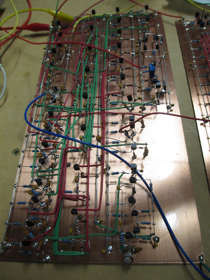
The board itself. I currently have a rather crappy ferrite-cored "choke" with a rather poo temperature coefficient soldered into the tank circuit of the master oscillator, as this is what immediately at hand. I'll will be sourcing a better core material to wind a better substitute.
