If those are connected, then everything else looks fine...
I went ahead and fixed them anyway. Turns out it's some sort of issue with how the nodes were reproduced when I copied/pasted various circuit blocks. (There's a lot of repeated circuit blocks, so it saves time to do it that way.)
Alternatively you can just add a jumper to select either the flip-flops Q or !Q.
I was considering tapping off the other side of the flip-flop but wanted to run it by you.
Timb, you forgot to label the Z axis output connector and will you be providing an optional inverted Z axis output? It would only require an additional transistor and 3 resistors.
The labeling is fixed in tonight's version. The Z-axis Inv will be added in the next version.
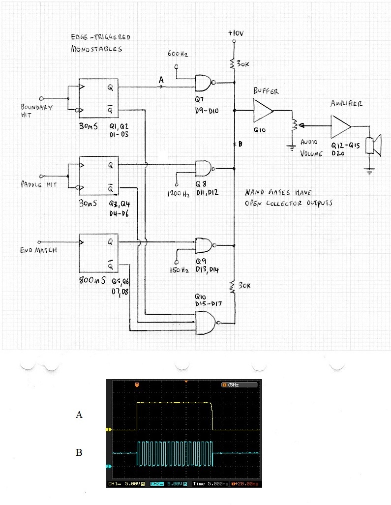
This is what I am currently working on and all pages/diagrams will eventually get collated into a single PDF document. Attached is the equiv. diagram of the sounds effects circuit:
Wow, that looks great! Feel free to share as you go along and I'll move it over to the digital schematic as well.
Okay, here's tonight's version of the schematic:
http://timb.us/PDF/Scope_Pong_20170328.pdfChanges:
Fixed connection between C606 and R640.
Fixed wire junctions. (I think I got these all, please point out any wires that connect without an appropriate (or shifted) callout.)
Changed polarized cap symbols.
Removed polarization symbol from bi-polar AE capacitor components.
Removed polarization sign silkscreen from bi-polar AE capacitor patterns.
Added part numbers and manufacturers to all items but ceramic caps and resistors in the BOM.
Added labeling per GK's schematic.


