Author Topic: Op amp testing circuit and unexpected behaviour on certain op amps  (Read 9016 times)

0 Members and 1 Guest are viewing this topic.

Offline LefunesteTopic starter

  • Contributor
  • Posts: 24
Hi guys,

Just a quick thread to get some ideas from the community about a design I am trying to implement.

As many of you around, I've always wondered, while repairing some piece of audio equipment, if any given op amp could be fried or not, and thus have always wanted to have a dedicated testing apparatus in order to test op amps.

So I've stumbled across several more or less refined designs on the web, and tried to implement this one :

http://www.seekic.com/blog/project_solutions/2011/08/18/OPAMP_TESTER.html
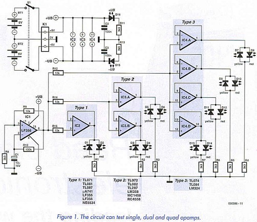


It is very simple in theory, it just produces a 1 Hz square wave with a simple RC oscillator, sends it to the DUT set at unity gain and uses the output to blink a pair of upside down LED on the up and down fronts of the wave.

So the design works well on all the op amps I have tested EXCEPT on some references I have : some SIP LM4558 and some NE5532 from China (source unconfirmed, may be fakes. I also have some original JRC5532 and these ones test OK !! So I guess the internal design is definitely different between these two of the same references). On these two op amps, only one LED per channel lights up and stays on (no blinking). I believe this is due to the internals of theses op amps which may have some diodes or other forms of protections making it impossible to sink (or source) current when the inverting input is shorted to the output of the op amp, such as in this design.

Can someone give me some ideas on ways to improve this design so that these op amps giving weird readings (and that I know are good) test properly ? Maybe I need to add some RC on the feedback loop or completely redesign the whole thing...

If you know any BETTER design for such a test I would be highly interested too ! I have not been able to find any really interesting and clever design around for such a simple test.

The circuit I am willing to design would have the following requirements :
-Just do a quick test GO/NO GO of as many op amps as possible.
-No measurements of characteristics is required. Just simple GO/NO GO of each channel.
-Be safe for all op amps.
-May be quite complex and require evolved parts (MCU, voltage conditioners...)

If someone has some idea, I'd be HIGHLY thankful !
 

Offline SeanB

  • Super Contributor
  • ***
  • Posts: 16373
  • Country: za
Re: Op amp testing circuit and unexpected behaviour on certain op amps
« Reply #1 on: May 10, 2014, 12:34:44 pm »
Take the voltage feed from across C1 and buffer it with another opamp and arrange the DUT's as a gain of 2 unit, so you can see the LED grow brighter and darker as it charges. Use a single 9V battery and use a simple voltage divider and another opamp as a buffer to give you a split rail of +-4V5, so you can test more modern opamps which only are rated for 5V rails. This needs 3 opamps to make, so you can just use a single quad opamp and simply use the unused one as a buffer for the split rail and feed the LED current back through it. No other reason for this than you have an unused one anyhow and it just will give it a function.
 

Offline LefunesteTopic starter

  • Contributor
  • Posts: 24
Re: Op amp testing circuit and unexpected behaviour on certain op amps
« Reply #2 on: May 10, 2014, 01:34:50 pm »
Hi Sean thanks for the quick reply. Yes I have some quads in my spare box I can use for that.

So if I understand you correctly, what you are saying is that instead of getting my square signal out of the oscillator op amp, I use the voltage across the cap C1. This would change the voltage swing of the square wave + Rail / - Rail (what I have now) to something like 2x Rail / 1x Rail . Then send this signal to a buffer op amp, then go to the DUT (set to a gain of 2) and have one LED only instead of two. The LED would then light Full and Half strength as the DUT is being tested.

Is this correct ?

Would this modified design solve the problem I have encountered with these weird op amps ? I really don't understand why these op amps react this way...

I leave the voltage split rail considerations for the moment as I will have this in my final design anyway using a dedicated rail splitter.
« Last Edit: May 10, 2014, 01:37:41 pm by Lefuneste »
 

Offline David Hess

  • Super Contributor
  • ***
  • Posts: 17241
  • Country: us
  • DavidH
Re: Op amp testing circuit and unexpected behaviour on certain op amps
« Reply #3 on: May 10, 2014, 01:37:24 pm »
Not all operational amplifiers are stable at unity or low gains; the OP-37 is a prime example of this.  It may be feasible to add external compensation to operate them this way though:

http://www.analog.com/library/analogdialogue/archives/38-06/capacitive_loading.html
http://www.ti.com/lit/an/snoa486b/snoa486b.pdf

Some operational amplifiers are going to be unhappy if their common mode voltage range is exceeded.  In particular, some JFET input operational amplifiers will suffer from phase reversal.

As a simple test, what I would do instead is drive the operational amplifiers with a relatively slow +/- 10 volt triangle wave (buffer the signal from the non-inverting input of your LF356) and use the LEDs to monitor the difference between the input and output of each operational amplifier.  Then if one lights, the output is not following the input so something is wrong.
 

Offline LefunesteTopic starter

  • Contributor
  • Posts: 24
Re: Op amp testing circuit and unexpected behaviour on certain op amps
« Reply #4 on: May 10, 2014, 01:39:57 pm »
Hi David, Thanks for your help.

Yes as a matter of fact both these opamps testing strangely are JFET indeed... I suspected these to be unstable at unity gain and have triggered some internal protection.

Your idea in quite interesting. I would have to design some LED + Transistor to monitor voltage difference so that I have one led lighting if input and output are in phase, and light another color LED if it's KO / out of phase. That's neat.
« Last Edit: May 10, 2014, 01:45:38 pm by Lefuneste »
 

Offline w2aew

  • Super Contributor
  • ***
  • Posts: 1780
  • Country: us
  • I usTa cuDnt speL enjinere, noW I aR wuN
    • My YouTube Channel
Re: Op amp testing circuit and unexpected behaviour on certain op amps
« Reply #5 on: May 10, 2014, 01:41:24 pm »
Not all operational amplifiers are stable at unity or low gains; the OP-37 is a prime example of this.  It may be feasible to add external compensation to operate them this way though:

http://www.analog.com/library/analogdialogue/archives/38-06/capacitive_loading.html
http://www.ti.com/lit/an/snoa486b/snoa486b.pdf

Some operational amplifiers are going to be unhappy if their common mode voltage range is exceeded.  In particular, some JFET input operational amplifiers will suffer from phase reversal.

As a simple test, what I would do instead is drive the operational amplifiers with a relatively slow +/- 10 volt triangle wave (buffer the signal from the non-inverting input of your LF356) and use the LEDs to monitor the difference between the input and output of each operational amplifier.  Then if one lights, the output is not following the input so something is wrong.

You took the words right out of my mouth (unity gain issues, phase reversal issues).
YouTube channel: https://www.youtube.com/w2aew
FAE for Tektronix
Technical Coordinator for the ARRL Northern NJ Section
 

Offline w2aew

  • Super Contributor
  • ***
  • Posts: 1780
  • Country: us
  • I usTa cuDnt speL enjinere, noW I aR wuN
    • My YouTube Channel
Re: Op amp testing circuit and unexpected behaviour on certain op amps
« Reply #6 on: May 10, 2014, 01:42:29 pm »
Hi David, yes as a matter of fact both these opamps testing strangely are JFET indeed... I suspected these to be unstable at unity gain and have triggered some internal protection.

If they're not unity gain stable, then they are likely oscillating - and at a high enough frequency that it simply looks like the LED(s) are on.
YouTube channel: https://www.youtube.com/w2aew
FAE for Tektronix
Technical Coordinator for the ARRL Northern NJ Section
 

Offline LefunesteTopic starter

  • Contributor
  • Posts: 24
Re: Op amp testing circuit and unexpected behaviour on certain op amps
« Reply #7 on: May 10, 2014, 01:49:38 pm »
Ah ah !! Yes This is what's happening I think !! The Led lights up constantly but is sort of very slightly pulsing (while still lighting up) at 1 Hz the more I lower the rails voltages. Below a certain rail voltage (like +/- 4.5V) the LED starts to flash for good at 1 Hz (but only this one LED).
So the op amp is oscillating above a certain rail voltage, and below this voltage, it doesn't like phase reversal indeed.
« Last Edit: May 10, 2014, 02:05:37 pm by Lefuneste »
 

Offline David Hess

  • Super Contributor
  • ***
  • Posts: 17241
  • Country: us
  • DavidH
Re: Op amp testing circuit and unexpected behaviour on certain op amps
« Reply #8 on: May 10, 2014, 05:09:43 pm »
There is another thing which can happen.  In dual and quad parts, the separate operational amplifiers may share bias circuits.  Exceeding the common mode input range on one or driving it into saturation (using it as a comparator) may screw up the bias for one or more of the others causing them to behave strangely.  Like phase reversal, this issue is not as common as it used to be.

There are other tests that would be needed to detect subtle problems.  ESD damage can degrade the input bias current and other input parameters.  It can also damage the output stage such that output current is limited.
 

Offline Bored@Work

  • Super Contributor
  • ***
  • Posts: 3932
  • Country: 00
Re: Op amp testing circuit and unexpected behaviour on certain op amps
« Reply #9 on: May 10, 2014, 05:31:22 pm »
For what it's worth, that circuit, including the schematic is a ripoff from Elector. Seekic never published something original.

And that circuit can be simplified. D1 ... D6, R1 ... R3, and two more resistors, can be removed. Just wire up the quad version. Then wire up the sockets for other pin configurations in parallel to the quad socket.
I delete PMs unread. If you have something to say, say it in public.
For all else: Profile->[Modify Profile]Buddies/Ignore List->Edit Ignore List


Share me

Digg  Facebook  SlashDot  Delicious  Technorati  Twitter  Google  Yahoo
Smf