Author Topic: Voltage regulator in current feedback topology  (Read 873 times)

0 Members and 1 Guest are viewing this topic.

Offline ZoliTopic starter

  • Frequent Contributor
  • **
  • Posts: 521
  • Country: ca
  • Grumpy old men
Voltage regulator in current feedback topology
« on: October 05, 2023, 12:57:11 am »
For quite some time I'm thinking about to design/make a lab supply, which passes the LED test1. In layman's terms, that means decent transient load performance with no/minimal output capacitors.
Last year October, the light bulb came on: try to adapt the current feedback topology to a lab-supply regulator. Since then, I'm playing simulation and experimenting with new ideas/parts/etc.
At this moment, I consider the design mature enough to present it to the public.
This idea/design is original AFAIK, therefore (I think)can be patented, which I want to prevent it by releasing as public domain; if I'm wrong on the subject of originality, I will gladly stand corrected and provide apologies to the original idea owners.
To make the subject even more clear: I claim ownership on the application of the current feedback idea in the single polarity/asymmetrical applications, that's what I'm releasing here in public domain.
The files:
CFB_PSU.asc - LTSpice simulation
opa810_a.zip - TI's OPA810 macro model, NOT included with LTSpice; the simulation uses two of them; the power connections used in simulation are reversed from the original.
CFBPSU_CAD.png - the original CAD(Carbon Aided Design) drawing >:D
PSU_SCchematix.png - the current schematic as time of writing
As it stands, the behaviour of the simulation is oriented to have fast reaction in CV mode; the fast CC mode is just bonus.
Feel free to ask questions, comment on the subject; I will try to give answers/reasons/ideas on the subject.
A few of screenshots previously posted in an other tread(https://www.eevblog.com/forum/projects/fast-cccv-power-supply-take-two/?all):
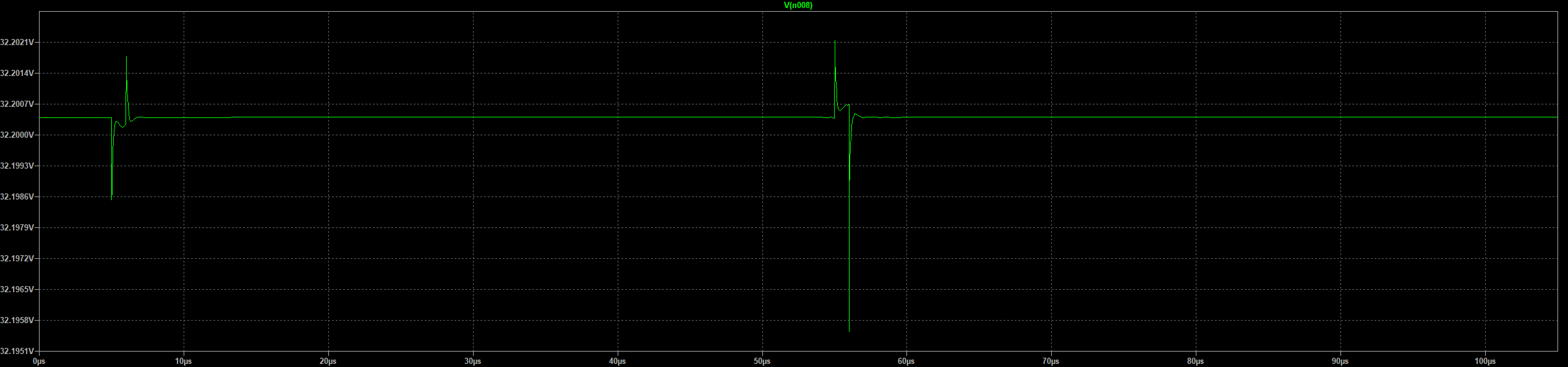
Reaction to a 1A->1.5A load change, current ramp 1A/µs

Same load, with a 330µF/50mΩ(ESR) capacitor on the output

Current limiting output

Current limit on the load(green) and on the sense resistor(blue) without output capacitor


1LED test: PSU output@max(>30V)&on, current limit@20mA, connect the LED, and the LED has to survive
 

Online David Hess

  • Super Contributor
  • ***
  • Posts: 17002
  • Country: us
  • DavidH
Re: Voltage regulator in current feedback topology
« Reply #1 on: October 05, 2023, 06:57:29 am »
What you are doing will work, but current feedback would be from the output of the pass transistor to the *output* of the operational amplifier.  The current feedback topology for a voltage feedback operational amplifier has two voltage feedback inputs, the inverting and non-inverting input, and a third current feedback input in the form of the output of the operational amplifier.

The 741 example below is in the oldest Fairchild datasheets from the 1970s, so current feedback with a voltage feedback operational amplifier it is hardly a new idea.

Tektronix used your configuration as shown below which provides a slew rate enhancement to the output through the supply pins.
« Last Edit: October 05, 2023, 07:02:06 am by David Hess »
 
The following users thanked this post: Vovk_Z

Offline magic

  • Super Contributor
  • ***
  • Posts: 7016
  • Country: pl
Re: Voltage regulator in current feedback topology
« Reply #2 on: October 05, 2023, 11:38:49 am »
Under what circumstances is Q2,Q1,Q3 current supposed to vary and how much?
I don't see the point of this mirror.
 

Online David Hess

  • Super Contributor
  • ***
  • Posts: 17002
  • Country: us
  • DavidH
Re: Voltage regulator in current feedback topology
« Reply #3 on: October 05, 2023, 12:37:01 pm »
Under what circumstances is Q2,Q1,Q3 current supposed to vary and how much?
I don't see the point of this mirror.

When the output voltage of operational amplifier U1 increases, more current flows from the positive supply pin to the negative supply controlled by the 243 ohm resistor which is missing from the simulation schematic.  That supply pin current drives the current mirror which reverses the current to drive the output transistor.

That resistor turns the voltage output of the operational amplifier into a current output from the operational amplifier's supply pins.
 

Offline magic

  • Super Contributor
  • ***
  • Posts: 7016
  • Country: pl
Re: Voltage regulator in current feedback topology
« Reply #4 on: October 05, 2023, 12:46:36 pm »
the 243 ohm resistor which is missing from the simulation schematic

Ah, makes sense. I was looking at that LTspice screenshot which is supposedly the "current schematic at time of writing".


Share me

Digg  Facebook  SlashDot  Delicious  Technorati  Twitter  Google  Yahoo
Smf