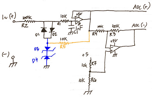
Attached is a drawing of the circuit I suggested, including protection.
Hi Kleinstein,
I've taken a good look at your schematic and I understand now what you were trying to say about driving the ADC(-) with the common mode voltage. Makes complete sense, so the full 5V range can be used. Its a pretty cool circuit you put together- I see you balanced the input and output resistance, set the common mode voltage, and provided reverse and over voltage protection! Awesome! I have a couple questions though...
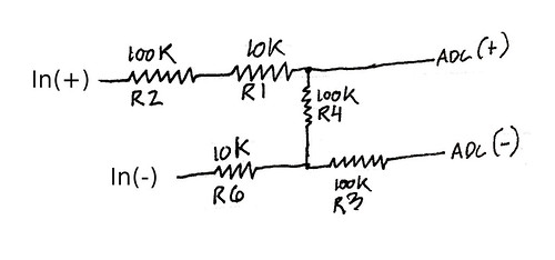
I redrew your schematic a couple times to better understand it:

Let me know if I am understanding anything incorrectly, here is what I got:
R2 provides some input protection, and R1 sets the bias current.
D1 and D2 provide reverse polarity protection
D3 and D4 limits the input voltage to their zener value +.7V
R7 and R6 provides the common mode voltage as well as Vin (-) input
common mode voltage is set at 2.5 between R3 and R4
R4 provides return path for bias current
R3 - not sure of purpose. Balance the resistance of Vin(-) leg with Vin(+) leg?
Here's the things Id like to better understand:
What is the function of the 10K resistor R5?
What value of zeners to use? Around 4V?
It looks like there could possible be leakage current on the input through the diode string, and I'm not sure if that has much of an effect- is there any way to limit the leakage current? Or is it negligible?
D1 and D2 diodes- what would you suggest? Bav199? I think I have some BAT54 on hand already.. or would regular silicon diode be better?
I re-drew my interpretation of an effective version of the circuit, let me know if I've understood what you intended correctly
