I'm putting together a precision voltmeter w/ a 24 bit ADC, and I'm struggling to get the buffer to the ADC correct. The ADC used is the LTC2440, with a 5V LTC6655 reference. The assembly has been completed, but I need to re-work the ADC input buffer section. Here's a few pictures:
The ADC and the LTC6655 are covered by the gold shields
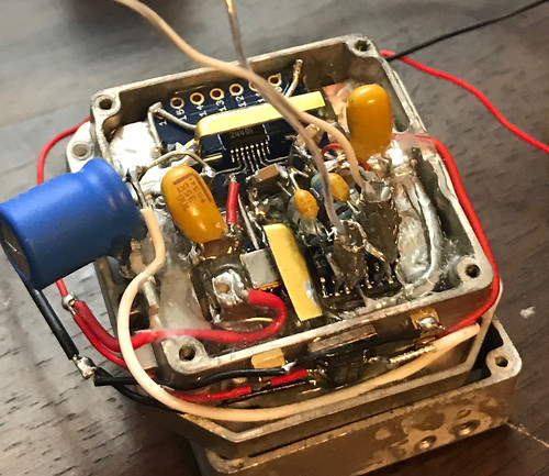
The analog and digital grounds are seperate, and the shield seperates the analog from the digital side
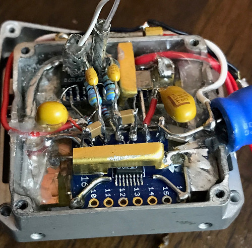
The 5V supply to the ADC is from an LT1461, and the (+) power supply to the buffers is from an LT3080. I'd like to use a single supply to the buffer amps if possible. Everything is powered from a 9V battery. The voltmeter is only used to measure positive DC voltages.
I'm having trouble with the input buffer to the ADC, specifically how to reference the differential inputs to the ground of the buffers. I'm somewhat new to op-amps. What I'm looking for is unity gain, and can handle a common mode voltage of +10-30 V. The desired output of the buffer is 0 -5 V. A little above 0 and a little less than 5 is ok and can be removed with calibration. On my first attempt I made the mistake picking opamps without taking into account how far they were able to swing compared to their power supply. So this is my second attempt. I went back to the datasheet for the 2440, and examined their buffer circuit using chopper amps:
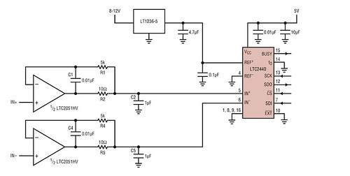
My plan is to use this circuit for the buffer, and I've got the LTC2051 here ready to use. To validate before installing, I made a test circuit using this schematic with LTC1050's, and found the output to bounce around wildly if the inputs didn't have a DC path to ground. A single supply of +6V was used for the 1050's, and a single AA battery of ~1.58 was applied to the inputs. I tried some other configurations as well, here's my results so far:
1) Referenced both inputs to ground using 10K resistors
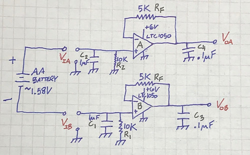
I measured the input voltages Via and Vib with reference to ground. Vib turned out to be negative and I quickly realized I had made a voltage divider with the center grounded:
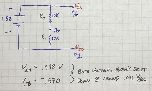
There isn't a negative supply so the output Vob was ~16 mV above ground, and Voa was ~1 V. No good. I was somewhat surprised to see the voltage wasn't split evenly. Maybe apply +2.5 V to the middle of R1 and R2 to correct the offset?
2) Removed the ground connection between R1 and R2
I've read the buffers always need a DC return for the inputs, so R1 and R2 were connected to each other, essentially floating relative to the buffer grounds:
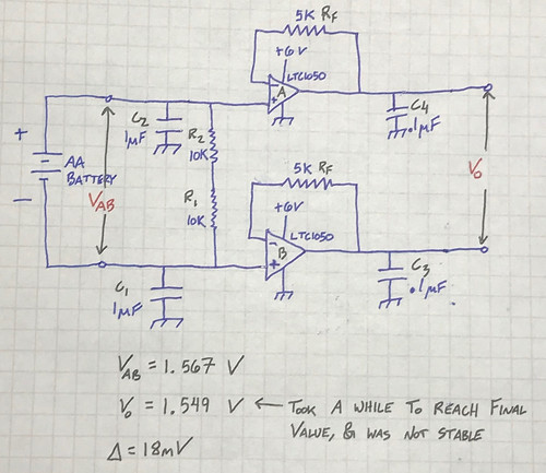
This produced better results, but it was clear the output was not very stable. It took quite some time to reach the final value, slowly rising to it. Blowing on the circuit would cause the output to jump 10-20 mV. Also, the offset of 18 mV, is that normal?
3) Grounded the battery to the buffer ground. This produced the best results
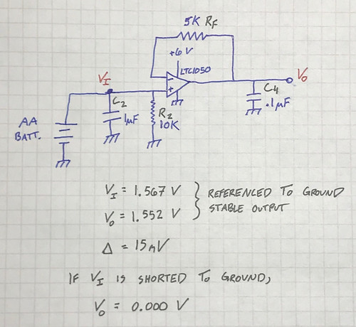
I see an offset of 15 mV again, is that a normal condition? The datasheet of the 1050 states an offset voltage of around 5 microvolts. If I'm doing something wrong here please let me know! Also if any of the passive component values are incorrect please advise. Circuit #3 produced the best results but ideally I'd like to avoid tying the V- input to ground. There is a high common mode voltage in the application, anywhere from 10-30VDC.
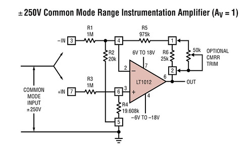
I've read through various datasheets looking for ideas, but I'm hoping someone more experienced than I can steer me in the right direction. Here's a few different buffer circuits I've found:
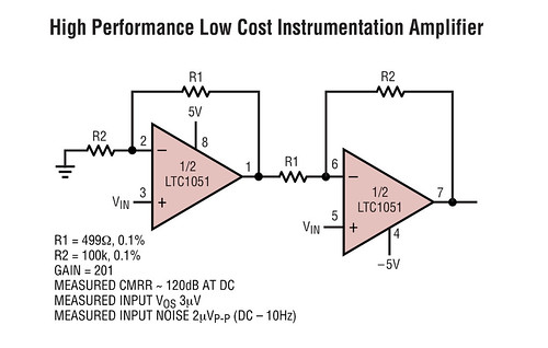
Looks like they get away with floating the inputs here?
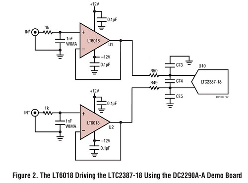
Interesting unity gain with CMRR trim
This circuit doesnt look all that different from my circuit #2, but with an added cap to ground
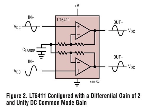
Any expertise you can offer would be very much appreciated! Thanks!