Author Topic: Nanoleaf Aurora teardown  (Read 90790 times)

0 Members and 2 Guests are viewing this topic.

Offline LaurentRTopic starter

  • Frequent Contributor
  • **
  • Posts: 536
  • Country: us
Nanoleaf Aurora teardown
« on: March 13, 2017, 03:15:05 am »
I really like the looks and idea of the Nanoleaf Aurora.


While I like what they have done with the app, I wanted to figure out how to drive it myself using some other method (Arduino...). I was also curious about how they built the tiles. They use a 4-wire communication link that is distributed through the tiles (GND, 20V, VBUS, EDGE according to the controller's PCB). One of the key feature of the Aurora is topology discovery, so I can only assume they have a custom protocol (at least on one of the pins).

The picture below shows how the tile is put together.
The bottom is a fairly strong white plastic bed.
In the groove, the PCB and LEDs run around the periphery (see images below).
There is the bottom layer diffuser layer, in thin white plastic.
On top sits a thick transparent block of plastic with a regular hole pattern.
Finally, the top is a frosted plastic that is glued around the edges to the bottom plastic chassis.
The corners, where the LEDs sit are covered by aluminum cutouts.


The following picture shows the triangular PCB (components on the bottom) running along the edges the plastic bottom with the 3 banks of LEDs at each corner.


This is one of the 3 banks of LEDs. It seems to be composed of 6 basic white LEDs connected in series, which turn on at power up and 6 smart LEDs in a 6-pin 5050 package. I assume they are WS2812, but I haven't checked yet.


The PCB is in reality 3 long strips soldered at each edge using an interesting S pattern, I assume to improve alignment. These seem to have been hansoldered as there was obvious flux residue.


Below is the whole PCB, components up. Most components are on one PCB. The board has mostly simple components except for one tiny 16 pin package, which I haven't identified yet (CPLD or microcontroller?). Notice the identical connectors on each edge to allow for the arbitrary topology.


Close-up:


The controller itself is an assembly of a green wifi module (Nanoleaf branded), possibly leverage from one of their other product on top of a white Aurora-specific PCB, with 2 buttons. The whole tile system runs on a 24V supply (they can power up to 30 panels according to the spec).


Wifi module:


That's all for now!

I made a rookie mistake while soldering external wiring between my tile and the controller and (stupidly) assumed that the 4-pin header on the tile PCB near the main spring-loaded connector was just a breakout of that connector, but it wasn't  :wtf:  at all.
So with 24V, the magic smoke appeared on the 16-pin package on the tile and the controller doesn't boot anymore

I am going to wait a bit and synthesize the funds to buy another kit.
I'll get back on the thread when I make actual progress in reverse engineering the protocol between the controller and the tiles |O  |O  |O
« Last Edit: March 19, 2017, 12:10:21 am by LaurentR »
 
The following users thanked this post: d1ode

Offline RainerG

  • Newbie
  • Posts: 1
  • Country: us
Re: Nanoleaf Aurora teardown
« Reply #1 on: March 14, 2017, 02:02:45 pm »
Thanks. I'm curious about the protocol.
 

Offline LaurentRTopic starter

  • Frequent Contributor
  • **
  • Posts: 536
  • Country: us
Re: Nanoleaf Aurora teardown
« Reply #2 on: April 10, 2017, 06:32:48 am »
Got a new one and have managed to spend a few hours looking into it (and didn't blow anything else so far...).

As mentioned above, the connector has 4 pins allowing for any topology (names from the controller PCB silkscreen):
* GND: Shared ground.
* 20V: 24V DC straight from the AC adapter - propagated as is between tiles.
* EDGE: 3.3V switched signal. It is the only signal that is not broadcast and seems to be used for topology discovery. Each node controls its 3 sides.
* VBUS: 24V rail-to-rail, 115,200 baud, half-duplex, 8-N-1, idle-high UART (see below) that is broadcast throughout the tiles

The controller board is single sided. See topology below.

Main content:
* 2 buttons connected to the daughterboard.
* A 3.3V switcher circuit on the right, that feeds the comparator and the daughterboard.
* A 2N7002K mosfet driving the VBUS signal low with a 4k7 pullup to 24V. Mosfet is controlled from an 2N2222, itslef driven by the daughterboard.
* A LM393 comparator used to read back the VBUS line (as it is half-duplex) to the daughterboard.


The tile PCB uses a Silicon Labs EFM8 "Busy Bee" BB1 in a QFN20 package. That's a tiny C8051 SoC with 512B of SRAM and 4KB of flash.
This is a bad news, because this means the tile is "smart" and the protocol can be fairly complex... which it is.

See picture of the (blown) BB10 below:
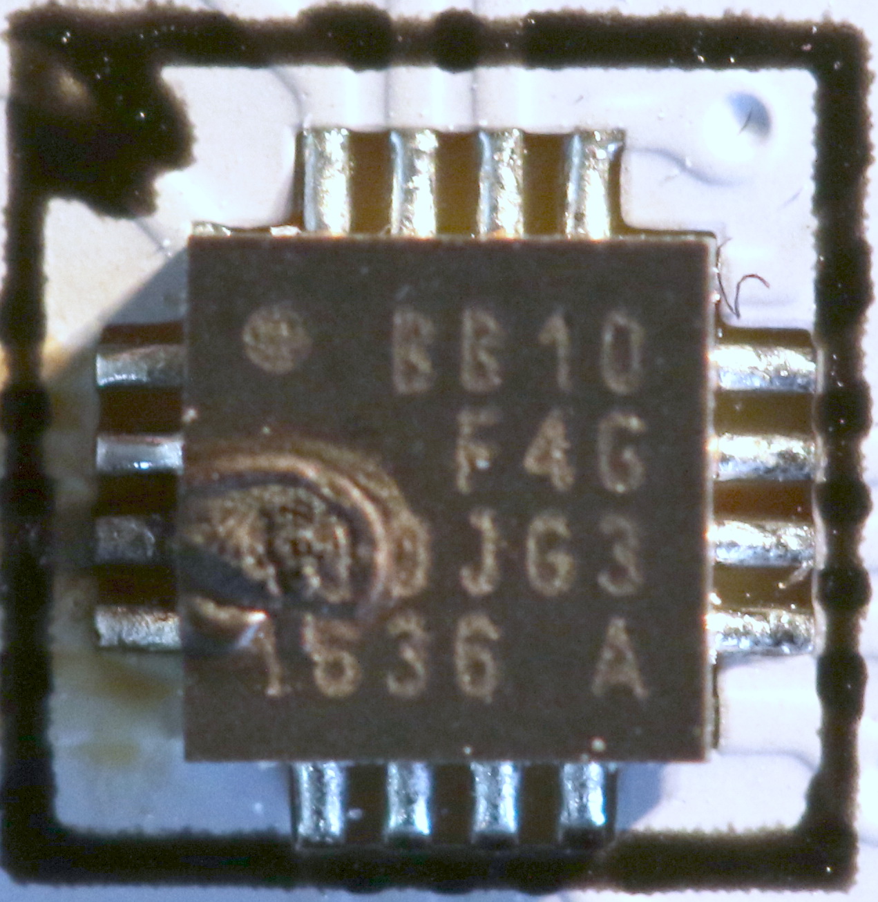


At this point, I have found 8 message types, 4 of which get a response (3 "ack" type ones with no data and one with a fair chunk of data).
Each tile has a unique byte address and the controller remembers it between boots. That byte address seems to unique to the tile, not the position, although it can be reprogrammed if the tiles change enough.

The boot sequence looks like this:
* For the first ~30sec, all tiles display white using the white LEDs and there is very little/no traffic on the VBUS. I assume the daughterboard microcontroller is booting, attaching to wifi...
* Then there is a complicate dance between the controller and the tiles, some messages including up to 11 bytes of data, which are not repeated much, so it is difficult to make sense of them. Clearly, the microcontroller is checking topology and updating it if necessary. I am not sure I'll be able to crack the boot.
* Finally, the tiles switch to the WS2812 and regular messages are sent by the controller to adjust colors plus some keep-alives. I haven't spent time on the color messages yet, but they seem straightforward and I should be able to map them out.

Now on the protocol details and how the EDGE signal is used...
« Last Edit: April 10, 2017, 06:40:12 am by LaurentR »
 

Offline mohammad

  • Newbie
  • Posts: 7
  • Country: ir
Re: Nanoleaf Aurora teardown
« Reply #3 on: September 13, 2017, 05:34:07 am »
hi, in Nanoleaf Aurora teardown ,what is u2?
 

Offline LaurentRTopic starter

  • Frequent Contributor
  • **
  • Posts: 536
  • Country: us
Re: Nanoleaf Aurora teardown
« Reply #4 on: September 13, 2017, 05:37:44 am »
hi, in Nanoleaf Aurora teardown ,what is u2?

On the controller board, U2 is the LM393 comparator used to read back the half-duplex 24V UART bus (VBUS). Not sure why they didn't simply use a resistor network to voltage divide down to 3.3V.
 

Offline mohammad

  • Newbie
  • Posts: 7
  • Country: ir
Re: Nanoleaf Aurora teardown
« Reply #5 on: September 13, 2017, 05:43:11 am »
What algorithm form the triangles in the software?
Sorry i have a bad conversation? :-[
 

Offline mohammad

  • Newbie
  • Posts: 7
  • Country: ir
Re: Nanoleaf Aurora teardown
« Reply #6 on: September 13, 2017, 05:48:57 am »
Will run with my my9942 IC. But How do I create an automatic shape?
 

Offline LaurentRTopic starter

  • Frequent Contributor
  • **
  • Posts: 536
  • Country: us
Re: Nanoleaf Aurora teardown
« Reply #7 on: September 13, 2017, 05:56:07 am »
What algorithm form the triangles in the software?
Sorry i have a bad conversation? :-[

Are you asking how they figure out the topology of the triangles?

I have done a bunch more reverse-engineering I haven't published yet.

For the topology discovery, they use the EDGE pin. While VBUS is UART half-duplex broadcast, EDGE is a simple level signal, purely point-to-point used only doing discovery. As they walk down the tree structure to discover it, they basically turn on one EDGE pin on an unexplored branch of the tree, then through the VBUS ask whichever tile is seeing EDGE=1 to respond. From that, they get a unique tile ID (factory programmed I believe), then use this to assign a short ID to that tile, so they can talk to it later. Then they keep going.

Note that they actually store the topology in the controller, so on subsequent reboots, they quickly "confirm" the topology and unless they find anything weird, they don't do a full walk. I ave seen that algorithm fail when moving some tiles around  ;D
 

Offline LaurentRTopic starter

  • Frequent Contributor
  • **
  • Posts: 536
  • Country: us
Re: Nanoleaf Aurora teardown
« Reply #8 on: September 13, 2017, 06:01:17 am »
Note that the protocol to bring up the tile network and start sending color change commands is fairly complex, even if you know the topology and don't have to discover it.
At some point, I'll finish publishing the reverse-engineered protocol, but I have been distracted by other projects these past few months.

If you want to tackle this, you'll need a good logic analyzer that can dump the VBUS traffic (UART) and a lot of patience.
 

Offline mohammad

  • Newbie
  • Posts: 7
  • Country: ir
Re: Nanoleaf Aurora teardown
« Reply #9 on: September 13, 2017, 07:11:30 am »
Thank you
 

Offline evilracer

  • Newbie
  • Posts: 1
  • Country: ca
Re: Nanoleaf Aurora teardown
« Reply #10 on: September 14, 2017, 06:11:04 pm »
Thanks for this @LaurentR. Is it possible for you to measure the thickness of the top layers (diffuser, transparent block, and the frosted panel)?
 

Offline LaurentRTopic starter

  • Frequent Contributor
  • **
  • Posts: 536
  • Country: us
Re: Nanoleaf Aurora teardown
« Reply #11 on: September 15, 2017, 06:01:34 am »
Thanks for this @LaurentR. Is it possible for you to measure the thickness of the top layers (diffuser, transparent block, and the frosted panel)?

The bottom, opaque white layer (some kind of plastified paper - maybe all plastic) is 0.34mm
The transparent block with the diffusing dots is 3.0mm
The frosted top layer is 0.50mm.
 

Offline mohammad

  • Newbie
  • Posts: 7
  • Country: ir
Re: Nanoleaf Aurora teardown
« Reply #12 on: September 17, 2017, 07:41:05 am »
hi dear ,Controller for nanowulf is dmx?
 

Offline LaurentRTopic starter

  • Frequent Contributor
  • **
  • Posts: 536
  • Country: us
Re: Nanoleaf Aurora teardown
« Reply #13 on: September 17, 2017, 04:23:01 pm »
hi dear ,Controller for nanowulf is dmx?

No, it's definitely not DMX. It uses a standard half-duplex UART protocol but the messages are completely proprietary.
 

Offline mohammad

  • Newbie
  • Posts: 7
  • Country: ir
Re: Nanoleaf Aurora teardown
« Reply #14 on: October 07, 2017, 09:39:59 am »
Hello. Good time. You did not investigate the lamp.
 

Offline tmk198

  • Newbie
  • Posts: 1
  • Country: gb
Re: Nanoleaf Aurora teardown
« Reply #15 on: November 30, 2017, 09:45:52 pm »
Hi I love the nanoleaf but I hate the stupid daughter board and trailing cable stuck to the side. I want to hide the daughter board in my loft and run a cable inside my wall. I am thinking due to the high current some 0.75mm flex with some cat 5 to carry the 2 control wires to minimise interference.

I note you managed to fry your first unit but didn't understand the mistake you made? I was just going to solder directly on to the copper contacts on the daughter boards. To connect in to the leaf from behind I was going to snap one of the connectors in half and then solder on to the underside of the connector pins.

Any tips?
 

Offline LaurentRTopic starter

  • Frequent Contributor
  • **
  • Posts: 536
  • Country: us
Re: Nanoleaf Aurora teardown
« Reply #16 on: November 30, 2017, 11:38:40 pm »
Hi I love the nanoleaf but I hate the stupid daughter board and trailing cable stuck to the side. I want to hide the daughter board in my loft and run a cable inside my wall. I am thinking due to the high current some 0.75mm flex with some cat 5 to carry the 2 control wires to minimise interference.

I note you managed to fry your first unit but didn't understand the mistake you made? I was just going to solder directly on to the copper contacts on the daughter boards. To connect in to the leaf from behind I was going to snap one of the connectors in half and then solder on to the underside of the connector pins.

Any tips?

The signalling being 24V and relatively low frequency (100kb/s), I am pretty sure you can extend the wiring quite a bit.

As far as the connectivity to the first tile and to the controller, I think what you're proposing is the right approach. You may want to consider where the traces and vias are to reduce the chance of shorting traces when cutting the small connector.

I fried mine by not being careful enough. The little connectors have a bit too much play in some cases and after multiple insertion and probing, the copper fingers of the connectors on the tiles can get misaligned a bit. That can result in a destructive short (and at 24V, nothing stands a chance).
 

Offline kronoshacker

  • Newbie
  • Posts: 2
  • Country: at
Re: Nanoleaf Aurora teardown
« Reply #17 on: January 24, 2018, 03:54:28 pm »
If you are still interested in the protocol between the tiles - I have documented it here: https://kronoshacker.blogspot.de/2018/01/playing-with-aurora-led-panels.html
 
The following users thanked this post: Someone, LaurentR, mjanich

Offline LaurentRTopic starter

  • Frequent Contributor
  • **
  • Posts: 536
  • Country: us
Re: Nanoleaf Aurora teardown
« Reply #18 on: January 25, 2018, 05:24:28 pm »
If you are still interested in the protocol between the tiles - I have documented it here: https://kronoshacker.blogspot.de/2018/01/playing-with-aurora-led-panels.html

Great job, thanks. I got 90% of this but never figured out the rest. For instance, I never could figure out what the periodic 09 (call for unconfigured tiles in your post) was about. I thought it would be some kind of beacon or timing alignment. How did you figure it out? Did you reverse-engineer this?

Did you build something to control the tiles?

Laurent
 

Offline LaurentRTopic starter

  • Frequent Contributor
  • **
  • Posts: 536
  • Country: us
Re: Nanoleaf Aurora teardown
« Reply #19 on: January 25, 2018, 05:42:34 pm »
I should also note that they came out in mid-2017 with a microphone extension for the tiles and I assume that has at least a message polling the level of the microphone. I did get one but haven't tried it yet.

https://us-shop.nanoleaf.me/products/nanoleaf-rhythm-upgrade-module
 

Offline kronoshacker

  • Newbie
  • Posts: 2
  • Country: at
Re: Nanoleaf Aurora teardown
« Reply #20 on: January 25, 2018, 11:56:57 pm »
Knowing from your post that the tiles speak RS232@24V, I built a simple crappy USB Interface using a cheap USB-to-RS232@3.3V Adapter and a voltage divider, a z-diode and a transistor.

Then I logged the traffic on a PC and slowly built up a simple protocol decoder in python. Finally, I replaced the original host tile and sent my own commands to figure out the details by trial and error.

Unfortunately there is no time sync. So you cannot change the color of multiple tiles at the same time...

I also have the rhythm extension. It enumerates similar to a normal tile, but returns a different version string. It just broadcasts the energy levels on different audio frequencies about 25 times/s. it is - very strange - not polled! But all the pattern and effects logic is in the original CPU tile. The rhythm tile is just a microphone + FFT. I’ll post the detailed protocol description soon.

Using a script that feeds the PCs sound output into a FFT and then emulating the rhythm tile, I get much better results for effects matching the sound than with the original mic.
 

Offline mjanich

  • Newbie
  • Posts: 2
  • Country: de
Re: Nanoleaf Aurora teardown
« Reply #21 on: January 26, 2018, 10:08:36 am »
I would like to make an Arduino or ESP8266 project out of this. Anyone interested?
 

Offline LaurentRTopic starter

  • Frequent Contributor
  • **
  • Posts: 536
  • Country: us
Re: Nanoleaf Aurora teardown
« Reply #22 on: January 26, 2018, 04:50:05 pm »
I would like to make an Arduino or ESP8266 project out of this. Anyone interested?

I was planning to do this (and a video with the teardown / reverse engineering of the protocol) but got sidetracked.
It should be fairly straightforward.

You could either prototype it on a PC using the language of your choice with a cheap USB Serial TTL board as kronoshacker has done, or grab an ATSAMD21 Arduino variant (lots of space and 2 UART - one for the Nanoleaf, one for debug) like an Adafruit Feather M0 (also has small prototyping area for the voltage divider, pullup and driver transistor) or really anything else that has a UART, a free GPIO (ESP8266 or ESP32, RPi...).

I had done quite a bit of protocol analysis by writing some C on a PC to interpret dumps captured by a Saleae LA, but obviously, you can do the same with a USB serial adapter. That's probably the easiest way to start.

I had planned to do this in Arduino C on a Feather M0 and may still do it at some point (I have a pile of tiles at home begging to be driven by something else than the off-the-shelf Nanoleaf controller).

Laurent
 

Offline mjanich

  • Newbie
  • Posts: 2
  • Country: de
Re: Nanoleaf Aurora teardown
« Reply #23 on: January 30, 2018, 11:13:51 am »
Arduino development system is also the one I'm most comfortable with.
I think a nano has enough CPU power and I have a few lying around. But I also have a teensy here, I think that is an M0 chip.
 

Offline childressda

  • Newbie
  • Posts: 1
  • Country: us
Re: Nanoleaf Aurora teardown
« Reply #24 on: January 30, 2018, 10:22:40 pm »
I am also currently working on this, but I am trying to make everything.  I want to do this as a project with our students.  I am using the ESP8266 so I can connect to it and change the tile colors.  I plan to connect a sound detector to use for changing the colors to music.  My plan is to have very little tech in the panels.  Basically, the panel will have the led lights, a comparator controlling a relay.  This is needed to continue the data out of a dead end tile back through its feeder panel.  The limiting factor will only be the power needs of the panel, 60ma / led.  Each panel will connect via a 3 pins 5v, Di, Grnd or 4 pins   5v, Di, Grnd, Db (DataBack). 

I have designed the panel to be 3d printed.  See the attached png.  I will be happy to share the stl if anyone wants it.  My next challenge is diffusing the leds.  I will be testing various methods in the next week or so.  If anyone has any suggestions, I will give them a try. 


Share me

Digg  Facebook  SlashDot  Delicious  Technorati  Twitter  Google  Yahoo
Smf