Got a new one and have managed to spend a few hours looking into it (and didn't blow anything else so far...).
As mentioned above, the connector has 4 pins allowing for any topology (names from the controller PCB silkscreen):
* GND: Shared ground.
* 20V: 24V DC straight from the AC adapter - propagated as is between tiles.
* EDGE: 3.3V switched signal. It is the only signal that is not broadcast and seems to be used for topology discovery. Each node controls its 3 sides.
* VBUS: 24V rail-to-rail, 115,200 baud, half-duplex, 8-N-1, idle-high UART (see below) that is broadcast throughout the tiles
The controller board is single sided. See topology below.
Main content:
* 2 buttons connected to the daughterboard.
* A 3.3V switcher circuit on the right, that feeds the comparator and the daughterboard.
* A 2N7002K mosfet driving the VBUS signal low with a 4k7 pullup to 24V. Mosfet is controlled from an 2N2222, itslef driven by the daughterboard.
* A LM393 comparator used to read back the VBUS line (as it is half-duplex) to the daughterboard.

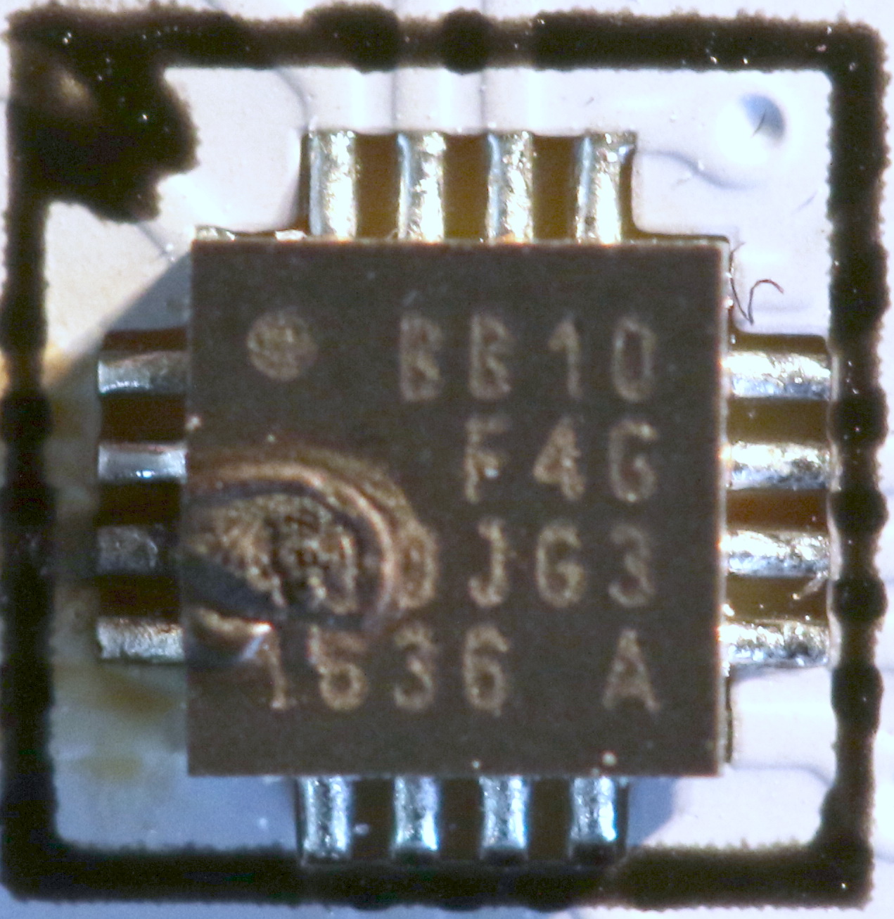
The tile PCB uses a Silicon Labs EFM8 "Busy Bee" BB1 in a QFN20 package. That's a tiny C8051 SoC with 512B of SRAM and 4KB of flash.
This is a bad news, because this means the tile is "smart" and the protocol can be fairly complex... which it is.
See picture of the (blown) BB10 below:

At this point, I have found 8 message types, 4 of which get a response (3 "ack" type ones with no data and one with a fair chunk of data).
Each tile has a unique byte address and the controller remembers it between boots. That byte address seems to unique to the tile, not the position, although it can be reprogrammed if the tiles change enough.
The boot sequence looks like this:
* For the first ~30sec, all tiles display white using the white LEDs and there is very little/no traffic on the VBUS. I assume the daughterboard microcontroller is booting, attaching to wifi...
* Then there is a complicate dance between the controller and the tiles, some messages including up to 11 bytes of data, which are not repeated much, so it is difficult to make sense of them. Clearly, the microcontroller is checking topology and updating it if necessary. I am not sure I'll be able to crack the boot.
* Finally, the tiles switch to the WS2812 and regular messages are sent by the controller to adjust colors plus some keep-alives. I haven't spent time on the color messages yet, but they seem straightforward and I should be able to map them out.
Now on the protocol details and how the EDGE signal is used...