Author Topic: Current measuring using LT6106  (Read 2739 times)

0 Members and 1 Guest are viewing this topic.

Offline Sudo_apt-get_install_yumTopic starter

  • Regular Contributor
  • *
  • Posts: 165
  • Country: se
Current measuring using LT6106
« on: March 23, 2018, 09:25:05 am »
Hi! I’m new to this forum!

So I’m working on a project were I’m interfacing with a few sensors that use "4-20mA" and Modbus to transmit data. I’m using the LT6106 to convert and amplify the 4-20mA signal from the current loop so that an AVR can read it with the ADC. I’m using the ATXMega128-B1. Yes I know I’m an AVR guy, screw PIC 8)

I’ve got the Modbus part working but I can’t seem to get the 4-20mA readings right.
The output from the LT6106 is nothing like it should be, I bogged a trim pot to adjust Rin and Rout, but nothing drastic happened.
I’ve also tried this in LTSpice and it shows a nice square wave on the output.

I would appreciate any feedback on this, I’m pulling my hair out because I can’t figure out what’s going on...

Il post schematic and a waveform from my scope.
« Last Edit: March 23, 2018, 09:32:00 am by Sudo_apt-get_install_yum »
 

Offline Jay_Diddy_B

  • Super Contributor
  • ***
  • Posts: 2765
  • Country: ca
Re: Current measuring using LT6106
« Reply #1 on: March 23, 2018, 12:29:52 pm »
Hi Sudo...,

Welcome to the forum !!

Let me see if I can help.

First you have significant differences in resistor values between the real schematic and the LTspice schematic:

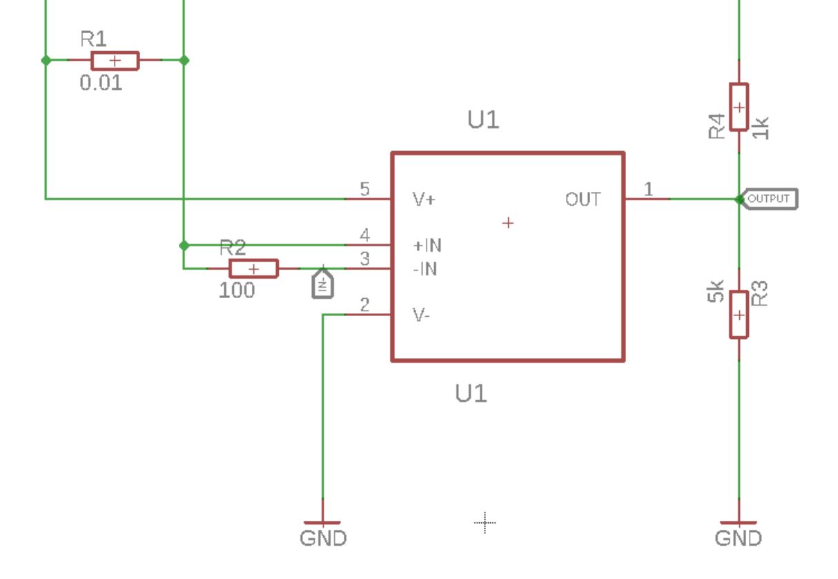


With reference to the real schematic, the current you are measuring flows through R1. With a 0.01 \$\Omega\$ resistor you will get 10uV of voltage for each mA of current. So in your application, 4-20mA, between 40uV and 200uV.

The LT6106 has a maximum offset specification of 250uV. The signal you are measuring is very small compared to the offset. This is not good, and will introduce large measurement errors.

This small signal is then amplified by the gain R3/R2

In the real schematic the gain is 5k/100 = 50

In the LTspice simulation the gain is 10K/10 = 1000

A big difference.

Modifications

First you should get your signal bigger. You do this by increasing the value of R1.

1 \$\Omega\$ will give you a signal of 4mV  to 20mV

And if you set the gain to 50, R3= 5k and R2 = 100, then the output signal will be 200mV to 1V for 4-20mA input.

If you need more accuracy, look at the zero-drift, LTC6102.

Regards,
Jay_Diddy_B

« Last Edit: March 23, 2018, 12:32:35 pm by Jay_Diddy_B »
 

Offline Sudo_apt-get_install_yumTopic starter

  • Regular Contributor
  • *
  • Posts: 165
  • Country: se
Re: Current measuring using LT6106
« Reply #2 on: March 23, 2018, 01:27:19 pm »
Thanks for the suggestions I changed the PCB values to the ones I used in LTSpice and it drastically changed thing (for the better).
The signal amplitude changes quite slowly but at least it changes. The "square wave" output from the LT6106 is very noisy and unstable so I tried using filter caps on the output but it didn’t do much but make the amplitude change much slower. Capacitor values I’ve tried 10nF-1µF

Reason why I can’t change R1 is because I don’t want to disrupt the signal since there might be things hooked up to the loop later on. Correct me if I’m wrong!

Is there anything you could do to get a clearer signal and retain a faster amplitude change or is the best I can get?

I’ve attached two pictures of the scope signal one at 4mA and one at 20mA.
 

Offline mikerj

  • Super Contributor
  • ***
  • Posts: 3336
  • Country: gb
Re: Current measuring using LT6106
« Reply #3 on: March 23, 2018, 01:39:09 pm »
Reason why I can’t change R1 is because I don’t want to disrupt the signal since there might be things hooked up to the loop later on. Correct me if I’m wrong!

1 Ohm resistor will only drop 20mV at full scale, if you can't budget for that in a 4-20mA loop then you have bigger problems to fix! 0.01 Ohms is simply too low to ever work well with the 6106 as Jay explained.
 

Offline Sudo_apt-get_install_yumTopic starter

  • Regular Contributor
  • *
  • Posts: 165
  • Country: se
Re: Current measuring using LT6106
« Reply #4 on: March 26, 2018, 12:10:59 pm »
Ok thanks for the help, I’m not too familiar to the "4-20mA" standard so I choose an incredibly small value to not disrupt any other device connected to the loop!
 

Offline glarsson

  • Frequent Contributor
  • **
  • Posts: 814
  • Country: se
Re: Current measuring using LT6106
« Reply #5 on: March 26, 2018, 12:18:16 pm »
The idea behind 4-20mA current loop standard us to handle long wires and voltage drops. As long as the driving voltage is high enough to drive 20mA it should work. BTW, some current loop devices even steal enough voltage drop to power themselves.
 

Offline Sudo_apt-get_install_yumTopic starter

  • Regular Contributor
  • *
  • Posts: 165
  • Country: se
Re: Current measuring using LT6106
« Reply #6 on: March 26, 2018, 12:33:51 pm »
I was actually thinking of making this project loop powered in the future or at least a loop powered meter of some sort. Could get the MCU to a few hundred µA during run time and a few µA during Power Down mode. I’m not really sure how ill display the data since Segment displays (LCD and LED) draw a few mA when running. But this is a problem for my future self.
 

Offline glarsson

  • Frequent Contributor
  • **
  • Posts: 814
  • Country: se
Re: Current measuring using LT6106
« Reply #7 on: March 26, 2018, 12:42:51 pm »
It should work as long as you don't draw so much current that the loop current enters the active range at 4mA.
 

Offline Sudo_apt-get_install_yumTopic starter

  • Regular Contributor
  • *
  • Posts: 165
  • Country: se
Re: Current measuring using LT6106
« Reply #8 on: March 27, 2018, 08:40:24 am »
I know I’m getting a bit off topic but any chance you can recommend some way to display the data; a few characters are fine as long as you can see number up to 999 or so.
7-Segment LED's are nice because of the contrast/easy to read and the same goes with segment LCD's.

Problem I have is that I’m not really finding displays that draw little current <1-4mA (Lower is better), I could always PWM the displays to get a dimmer effect but I’m not really sure if it’s the best way. Or if I could use the WDT and go to sleep every 8ms wake up and display the data and go back to sleep for another 8ms or longer intervals but not enough to see the pulsing. Sort of pulsing the MCU in and out of sleep, not really sure if it’s a good solution for power control, never done it before, just used the WDT to get in and out of sleep.

But this is just in the idea stage so it’s more of a problem in the future!
 

Offline jbb

  • Super Contributor
  • ***
  • Posts: 1237
  • Country: nz
Re: Current measuring using LT6106
« Reply #9 on: March 28, 2018, 08:17:39 am »
A modern micro (MSP430, EM32, probably some STM32 and NXP parts) with a built in LCD segment driver could work on much less than 1mA.

Texas Instruments (and presumably others) have some app notes about 4-20mA transmitters.

I would suggest you shoot for 2mA max consumption so that you can send an out-of range signal (some industrial systems can flag this as an error) and/or you’ve got some headroom for surprises.

Also note that flash memory erases and writes can suck down quite a bit of current.


Share me

Digg  Facebook  SlashDot  Delicious  Technorati  Twitter  Google  Yahoo
Smf