Author Topic: Measuring difference current between live and neutral?  (Read 18361 times)

0 Members and 14 Guests are viewing this topic.

Offline FaringdonTopic starter

  • Super Contributor
  • ***
  • Posts: 2088
  • Country: gb
Measuring difference current between live and neutral?
« on: August 19, 2021, 02:17:31 pm »
Hi,
We have live and neutral wires going through a torroid aperture, each carrying 16A maximum
The torroid is wound with a 100 turn coil.

Whenever live and neutral currents are not the same, there is obviously an output on the 100 turn coil.
We wish to tell when the live and neutral conductors are >30mA (RMS) different. (ie, its an RCD function)

Whats the best/smallest circuit to allow this measurement? (measuement will be by ADC of micro)?

We obviously cant diode rectify the coil output it as the diode drop would give inaccuracy.
Obviously when the live and neutral are 30mA in difference, we will get an output of 300uA out of the coil.
« Last Edit: August 19, 2021, 02:43:16 pm by Faringdon »
'Perfection' is the enemy of 'perfectly satisfactory'
 

Online Ian.M

  • Super Contributor
  • ***
  • Posts: 12946
Re: Measuring difference current between live and neutral?
« Reply #1 on: August 19, 2021, 02:42:55 pm »
You want to put a MCU in a RCD?   :scared:  :palm:
Do you have *ANY* experience with writing safety critical software?  :popcorn:
 
The following users thanked this post: nuclearcat, Faringdon

Offline coppice

  • Super Contributor
  • ***
  • Posts: 8909
  • Country: gb
Re: Measuring difference current between live and neutral?
« Reply #2 on: August 19, 2021, 02:51:32 pm »
You want to put a MCU in a RCD?   :scared:  :palm:
Do you have *ANY* experience with writing safety critical software?  :popcorn:
There are plenty of MCUs in RCDs these days, and I've yet to see people developing them have any real expertise in safety critical systems.
 
The following users thanked this post: Ian.M, Faringdon

Offline Siwastaja

  • Super Contributor
  • ***
  • Posts: 8288
  • Country: fi
Re: Measuring difference current between live and neutral?
« Reply #3 on: August 19, 2021, 03:01:15 pm »
You mistyped seriously indicating you are not up to this task.

It's line and neutral.

"Live and neutral" makes absolutely no sense because neutral is live as well. "Live" is an attribute attached to line and neutral wires, but not to the protective earth (PE).
 
The following users thanked this post: Faringdon

Online Ian.M

  • Super Contributor
  • ***
  • Posts: 12946
Re: Measuring difference current between live and neutral?
« Reply #4 on: August 19, 2021, 03:26:15 pm »
You want to put a MCU in a RCD?   :scared:  :palm:
Do you have *ANY* experience with writing safety critical software?  :popcorn:
There are plenty of MCUs in RCDs these days, and I've yet to see people developing them have any real expertise in safety critical systems.
Thank you for that worrying contribution.  I'm glad I don't and have never trusted RCDs to save my life.  At best they improve your odds of not dying and force you to fix high leakage faults before you get shocked by something that subsequently has developed a broken ground.

However I wouldn't trust a RCD designed and coded by Treez enough to prod it with anything shorter than a 10' bargepole (made of insulating epoxy/glass composite, not  traditional soggy wood or modern high tech aluminum or carbon fibre)!
« Last Edit: August 19, 2021, 04:40:18 pm by Ian.M »
 
The following users thanked this post: SeanB, Andy Watson, Gyro, Faringdon

Offline nali

  • Frequent Contributor
  • **
  • Posts: 676
  • Country: gb
Re: Measuring difference current between live and neutral?
« Reply #5 on: August 19, 2021, 03:33:21 pm »
You mistyped seriously indicating you are not up to this task.

It's line and neutral.

"Live and neutral" makes absolutely no sense because neutral is live as well. "Live" is an attribute attached to line and neutral wires, but not to the protective earth (PE).

Actually "Live" is normally often used here in the UK...

E.g.
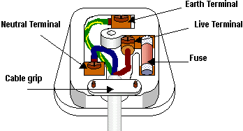
« Last Edit: August 19, 2021, 04:17:36 pm by nali »
 
The following users thanked this post: Faringdon

Online themadhippy

  • Super Contributor
  • ***
  • Posts: 2768
  • Country: gb
Re: Measuring difference current between live and neutral?
« Reply #6 on: August 19, 2021, 03:34:18 pm »
Quote
It's line and neutral.
surely you mean phase and neutral
 
The following users thanked this post: Faringdon

Offline Gyro

  • Super Contributor
  • ***
  • Posts: 9718
  • Country: gb
Re: Measuring difference current between live and neutral?
« Reply #7 on: August 19, 2021, 03:38:17 pm »
No, the wiring regs refer to it as Line (for domestic anyway).

... and Earth is now CPC of course.
« Last Edit: August 19, 2021, 05:08:25 pm by Gyro »
Best Regards, Chris
 
The following users thanked this post: Faringdon

Offline Gyro

  • Super Contributor
  • ***
  • Posts: 9718
  • Country: gb
Re: Measuring difference current between live and neutral?
« Reply #8 on: August 19, 2021, 03:41:46 pm »
You want to put a MCU in a RCD?   :scared:  :palm:
Do you have *ANY* experience with writing safety critical software?  :popcorn:
There are plenty of MCUs in RCDs these days, and I've yet to see people developing them have any real expertise in safety critical systems.
Thank you for that worrying contribution.  I'm glad I don't and have never trusted RCDs to save my life.  At best they improve your odds of not dying and force you to fix high leakage faults before you get shocked by something that subsequently has developed a broken ground.

However I wouldn't trust a RCD designed and coded by Treez enough to prod it with anything shorter than a 10' bargepole (made of insulating epoxy/glass composite, not  traditional soggy wood or modern high tech aluminum or carbon fibre)!

I notice that Andersen no longer trust (or have had distrust imposed upon them!) their 'internal RCD' and now require their charge point to be fed from a Type A RCBO in the consumer unit. 

Of course they've hidden it in the fine print of a manual update.
« Last Edit: August 19, 2021, 03:43:59 pm by Gyro »
Best Regards, Chris
 
The following users thanked this post: Faringdon

Online themadhippy

  • Super Contributor
  • ***
  • Posts: 2768
  • Country: gb
Re: Measuring difference current between live and neutral?
« Reply #9 on: August 19, 2021, 04:00:37 pm »
Quote
No, the wiring regs refer to it as Line
until the 19th when it will get changed again,cpc has at least been constant for 3 or 4 editions.
 
The following users thanked this post: Gyro, Faringdon

Offline uer166

  • Frequent Contributor
  • **
  • Posts: 919
  • Country: us
Re: Measuring difference current between live and neutral?
« Reply #10 on: August 19, 2021, 06:51:30 pm »
You want to put a MCU in a RCD?   :scared:  :palm:
Do you have *ANY* experience with writing safety critical software?  :popcorn:
There are plenty of MCUs in RCDs these days, and I've yet to see people developing them have any real expertise in safety critical systems.

I have some experience developing RCDs with a bunch of code/DSP, modern requirements make it mostly inevitable, you can't really do it in analog anymore. There are a lot of regulatory requirements that need to be met, I'm sure Treez's head would explode. Class B/UL991/UL1998. Things like checking all the CPU registers for stuck bits, continuous self-tests of RAM, redundancy where it matters, and full FMEAs that involve hundreds and hundreds of individual tests, and failsafes in case any component on the hardware fails in any way. All I can say is good fkn luck!
 
The following users thanked this post: Ian.M, nightfire, Faringdon

Offline Rod

  • Contributor
  • Posts: 31
  • Country: us
Re: Measuring difference current between live and neutral?
« Reply #11 on: August 19, 2021, 10:37:43 pm »
We wish to tell when the live and neutral conductors are >30mA (RMS) different. (ie, its an RCD function)

This is precisely what any ground-fault interrupter (GFCI outlet or breaker) does, although by NEC code they must trip at <10 ma difference between line and neutral... so perhaps you might simply buy one?
 
The following users thanked this post: Faringdon

Online themadhippy

  • Super Contributor
  • ***
  • Posts: 2768
  • Country: gb
Re: Measuring difference current between live and neutral?
« Reply #12 on: August 19, 2021, 11:06:57 pm »
Quote
This is precisely what any ground-fault interrupter (GFCI outlet or breaker) does
Or a Residual Current Device in the op's country of residence, gfci is a bit of a daft name considering  you can get them to trip by  methods that dont need a  fault to ground
Quote
NEC code
is not applicable in the uk
 
The following users thanked this post: Faringdon

Offline james_s

  • Super Contributor
  • ***
  • Posts: 21611
  • Country: us
Re: Measuring difference current between live and neutral?
« Reply #13 on: August 20, 2021, 06:03:20 am »
Or a Residual Current Device in the op's country of residence, gfci is a bit of a daft name considering  you can get them to trip by  methods that dont need a  fault to ground

You can also get a fire extinguisher to do something that doesn't involve putting out a fire. They're called GFCIs (here) because they're designed to interrupt the circuit in the case of a ground fault. That doesn't mean nothing else will cause them to trip, but that's what they're designed to do.
 
The following users thanked this post: Faringdon

Offline Zero999

  • Super Contributor
  • ***
  • Posts: 19671
  • Country: gb
  • 0999
Re: Measuring difference current between live and neutral?
« Reply #14 on: August 20, 2021, 09:59:10 am »
I think the point was: please take into consideration the original poster's location.

I thought RCDs have to trip on DC, as well as AC nowadays, because there's a lot of equipment which has a rectifier and it's important to detect any leakage on the DC side.

You can get Hall effect sensor modules, which monitor both AC and DC leakage.
http://www.multimic.com/e/products/detail/1791
https://www.technoteam.eu/en/non-split-type-current-sensors/16383-current-sensor-through-hole-type-leakage-acdc-200ma.html

Anyway, it's trivial to bias a bipolar signal around 1.5V or 2.5V, so it can be read by a microcontroller's ADC input.
 
The following users thanked this post: Faringdon

Offline FaringdonTopic starter

  • Super Contributor
  • ***
  • Posts: 2088
  • Country: gb
Re: Measuring difference current between live and neutral?
« Reply #15 on: August 20, 2021, 10:33:42 am »
Quote
Anyway, it's trivial to bias a bipolar signal around 1.5V or 2.5V, so it can be read by a microcontroller's ADC input.
Thanks yes, and we coudl amplify it up with INAMPS, and then precision rectify it...the thing is , we need to detect the imbalance current as accurately as possible first.
We wonder whether we should use an imbalance CT of iron, iron laminate, powdered iron, or ferrite, and if ferrite, NiZn, or Mn Zn?
'Perfection' is the enemy of 'perfectly satisfactory'
 

Offline Zero999

  • Super Contributor
  • ***
  • Posts: 19671
  • Country: gb
  • 0999
Re: Measuring difference current between live and neutral?
« Reply #16 on: August 20, 2021, 10:50:36 am »
Quote
Anyway, it's trivial to bias a bipolar signal around 1.5V or 2.5V, so it can be read by a microcontroller's ADC input.
Thanks yes, and we coudl amplify it up with INAMPS, and then precision rectify it...the thing is , we need to detect the imbalance current as accurately as possible first.
We wonder whether we should use an imbalance CT of iron, iron laminate, powdered iron, or ferrite, and if ferrite, NiZn, or Mn Zn?
The links I gave are to Hall effect sensors. Both live and neutral wires go through the same hole. Under normal operation, the magnetic fields produced by the currents cancel, but if there's a leakage, it's not cancelled and measured by the sensor.

There is no need for any instrumentation amplifiers and rectifiers. A single op-amp, with some resistors can perform level shifting and amplification and the rectification done in software.

Example:

Output voltage from the transducer =  +/-1.2V
Voltage required for MCU ADC input: 0V to 5V
Reference voltage: 5V

Using the calculators on the website linked below:
http://earmark.net/gesr/opamp/gain_offset.htm
http://earmark.net/gesr/opamp/case1b.htm

Enter:
Vin zero scale = 0
Vin full scale = 1.2V
Vout zero scale = 2.5V
Vref = 5V

Gives the following circuit:


Rf = 68k
Rg = 43k
R1 = 18k
R2 = 75k
 
The following users thanked this post: Faringdon

Online Circlotron

  • Super Contributor
  • ***
  • Posts: 3229
  • Country: au
Re: Measuring difference current between live and neutral?
« Reply #17 on: August 20, 2021, 11:53:00 am »
We obviously cant diode rectify the coil output it as the diode drop would give inaccuracy.
Obviously when the live and neutral are 30mA in difference, we will get an output of 300uA out of the coil.
Yes you can rectify the current transformer output without diode voltage drop causing any inaccuracy. The CT output is a current source, 300uA as you have stated, so it will within reasonable limits put out whatever voltage is necessary to produce that 300uA.  Just make sure you have the burden resistor after the diodes, not before.
 
The following users thanked this post: Faringdon

Offline Siwastaja

  • Super Contributor
  • ***
  • Posts: 8288
  • Country: fi
Re: Measuring difference current between live and neutral?
« Reply #18 on: August 21, 2021, 07:18:24 am »
Actually "Live" is normally often used here in the UK...

E.g.


Yeah, you'll find a lot of such examples.

Because something is a common mistake doesn't make it right; quite the opposite, it's even stronger reason to spend effort trying to set the record straight. This is safety critical terminology mistake. And terminology is important because that connects to our thinking, which affects our assumptions.

It's a common misassumption that neutral is "safe" because it's not "live", and this only originates from people accidentally labeling the other wire "live". This false assumption kills people, because line and neutral are often swapped, either completely legally in nonpolarized plugs, or due to fairly usual installation mistakes. So both wires need to be considered live regardless of color or label; if you don't, you are taking a serious risk up to 50% in case of nonpolarized plugs.

That's also the reason why PE is made so different; color is nowadays a special two-color mix which makes us pay special attention; the prong(s) in the plug is/are located in such way they stand out and swapping PE with anything else is visually obvious. Yet even with these precautions, swapping PE with either of the live wires does happen and people die as a result. It's just that swapping line and neutral is like 100 or 1000 times more common.

Quote
It's line and neutral.
surely you mean phase and neutral

Depending on country, yes. "Phase and neutral" or "Line and neutral". Line is a crappy word because it's too easy to mix with live, I'd prefer "phase" everywhere. In three-phase systems, L1, L2, L3 refer to three lines. On the other hand, phases are often called U,V,W. Same thing, different names.
 
The following users thanked this post: Faringdon

Offline Zero999

  • Super Contributor
  • ***
  • Posts: 19671
  • Country: gb
  • 0999
Re: Measuring difference current between live and neutral?
« Reply #19 on: August 21, 2021, 01:54:16 pm »
Actually "Live" is normally often used here in the UK...

E.g.


Yeah, you'll find a lot of such examples.

Because something is a common mistake doesn't make it right; quite the opposite, it's even stronger reason to spend effort trying to set the record straight. This is safety critical terminology mistake. And terminology is important because that connects to our thinking, which affects our assumptions.

It's a common misassumption that neutral is "safe" because it's not "live", and this only originates from people accidentally labeling the other wire "live". This false assumption kills people, because line and neutral are often swapped, either completely legally in nonpolarized plugs, or due to fairly usual installation mistakes. So both wires need to be considered live regardless of color or label; if you don't, you are taking a serious risk up to 50% in case of nonpolarized plugs.

That's also the reason why PE is made so different; color is nowadays a special two-color mix which makes us pay special attention; the prong(s) in the plug is/are located in such way they stand out and swapping PE with anything else is visually obvious. Yet even with these precautions, swapping PE with either of the live wires does happen and people die as a result. It's just that swapping line and neutral is like 100 or 1000 times more common.

Quote
It's line and neutral.
surely you mean phase and neutral

Depending on country, yes. "Phase and neutral" or "Line and neutral". Line is a crappy word because it's too easy to mix with live, I'd prefer "phase" everywhere. In three-phase systems, L1, L2, L3 refer to three lines. On the other hand, phases are often called U,V,W. Same thing, different names.
It's not an error. Phase, or line, was always called live in older standards and documentation. The terms have just changed over time, with the intention of making it easier to understand.

It's actually quite unusual for live and neutral to be swapped in the UK, because installations are always checked before being signed off. In older installations, without RCDs, it's also possible for the neutral and earth to be swapped and it will carry on working without any problem. The only time the neutral is hazardous, is if it''s broken.

I do agree one shouldn't assume the neutral conductor is safe to touch, but there's nothing wrong with using the term "live" to denote the phase conductor. It may be a little archaic, but it's still correct.


Quote
Anyway, it's trivial to bias a bipolar signal around 1.5V or 2.5V, so it can be read by a microcontroller's ADC input.
Thanks yes, and we coudl amplify it up with INAMPS, and then precision rectify it...the thing is , we need to detect the imbalance current as accurately as possible first.
We wonder whether we should use an imbalance CT of iron, iron laminate, powdered iron, or ferrite, and if ferrite, NiZn, or Mn Zn?
The links I gave are to Hall effect sensors. Both live and neutral wires go through the same hole. Under normal operation, the magnetic fields produced by the currents cancel, but if there's a leakage, it's not cancelled and measured by the sensor.

There is no need for any instrumentation amplifiers and rectifiers. A single op-amp, with some resistors can perform level shifting and amplification and the rectification done in software.

Example:

Output voltage from the transducer =  +/-1.2V
Voltage required for MCU ADC input: 0V to 5V
Reference voltage: 5V
I've just realised, the sensor I linked to gives +/-1.2V out, relative to a reference terminal, so no level shifting is required. Presumably the reference is around 2.5V, so you'll get 1.3V to 3.7V out. A non-inverting amplifier, with a gain of 2 could be used to give 0.1V to 4.9V out, but it's probably not worth it.

http://www.multimic.com/e/products/detail/1791
 
The following users thanked this post: Faringdon

Offline james_s

  • Super Contributor
  • ***
  • Posts: 21611
  • Country: us
Re: Measuring difference current between live and neutral?
« Reply #20 on: August 22, 2021, 06:44:52 am »
Depending on country, yes. "Phase and neutral" or "Line and neutral". Line is a crappy word because it's too easy to mix with live, I'd prefer "phase" everywhere. In three-phase systems, L1, L2, L3 refer to three lines. On the other hand, phases are often called U,V,W. Same thing, different names.
It's not an error. Phase, or line, was always called live in older standards and documentation. The terms have just changed over time, with the intention of making it easier to understand.

It's actually quite unusual for live and neutral to be swapped in the UK, because installations are always checked before being signed off. In older installations, without RCDs, it's also possible for the neutral and earth to be swapped and it will carry on working without any problem. The only time the neutral is hazardous, is if it''s broken.

I do agree one shouldn't assume the neutral conductor is safe to touch, but there's nothing wrong with using the term "live" to denote the phase conductor. It may be a little archaic, but it's still correct.
[/quote]

I've always either called it "hot" or "live" and neutral. The term "neutral" itself suggests that it is not (normally) live but that doesn't mean it's safe to touch. I would never assume the polarity of the wires in anything that plugs into a receptacle as I've seen those wired backwards a few times but as of yet I have never encountered a neutral wire in the built in wiring of a structure that was the wrong way around. What I have seen is white wires that are actually hot but not marked as such. This happens when a light is wired up with power going into the light box and a separate switch drop. It's also legal to use standard Romex with black and white conductors on N 240V
 
The following users thanked this post: Faringdon

Offline james_s

  • Super Contributor
  • ***
  • Posts: 21611
  • Country: us
Re: Measuring difference current between live and neutral?
« Reply #21 on: August 22, 2021, 06:48:31 am »
It's not an error. Phase, or line, was always called live in older standards and documentation. The terms have just changed over time, with the intention of making it easier to understand.

It's actually quite unusual for live and neutral to be swapped in the UK, because installations are always checked before being signed off. In older installations, without RCDs, it's also possible for the neutral and earth to be swapped and it will carry on working without any problem. The only time the neutral is hazardous, is if it''s broken.

I do agree one shouldn't assume the neutral conductor is safe to touch, but there's nothing wrong with using the term "live" to denote the phase conductor. It may be a little archaic, but it's still correct.


I've always either called it "hot" or "live" and neutral. The term "neutral" itself suggests that it is not (normally) live but that doesn't mean it's safe to touch. I would never assume the polarity of the wires in anything that plugs into a receptacle as I've seen those wired backwards a few times but as of yet I have never encountered a neutral wire in the built in wiring of a structure that was the wrong way around. What I have seen is white wires that are actually hot but not marked as such. This happens when a light is wired up with power going into the light box and a separate switch drop. It's also legal to use standard Romex with black and white conductors on North American 240V where both wires are live. In these cases the white wire is supposed to be marked with colored tape but that wasn't always required. Obviously that won't be an issue in the UK.
 
The following users thanked this post: Faringdon

Offline Zero999

  • Super Contributor
  • ***
  • Posts: 19671
  • Country: gb
  • 0999
Re: Measuring difference current between live and neutral?
« Reply #22 on: August 22, 2021, 07:51:02 am »
It's not an error. Phase, or line, was always called live in older standards and documentation. The terms have just changed over time, with the intention of making it easier to understand.

It's actually quite unusual for live and neutral to be swapped in the UK, because installations are always checked before being signed off. In older installations, without RCDs, it's also possible for the neutral and earth to be swapped and it will carry on working without any problem. The only time the neutral is hazardous, is if it''s broken.

I do agree one shouldn't assume the neutral conductor is safe to touch, but there's nothing wrong with using the term "live" to denote the phase conductor. It may be a little archaic, but it's still correct.


I've always either called it "hot" or "live" and neutral. The term "neutral" itself suggests that it is not (normally) live but that doesn't mean it's safe to touch. I would never assume the polarity of the wires in anything that plugs into a receptacle as I've seen those wired backwards a few times but as of yet I have never encountered a neutral wire in the built in wiring of a structure that was the wrong way around. What I have seen is white wires that are actually hot but not marked as such. This happens when a light is wired up with power going into the light box and a separate switch drop. It's also legal to use standard Romex with black and white conductors on North American 240V where both wires are live. In these cases the white wire is supposed to be marked with colored tape but that wasn't always required. Obviously that won't be an issue in the UK.
We have the same issue of light switches in the UK. The switch has twin and earth cable, with brown and blue insulation, the latter normally used for neutral, but will be live in this case. It's also mandatory to put a brown marker, over the blue wire, but this wasn't always the case. I've always thought it should be obvious that both conductors in a light switch are live, but there's no harm in adding a marker.

Obviously 230V isn't an issue, but 110VAC is sometimes used here on building sites and in some industrial situations. It's supplied by a centre tapped (single phase), or a star connected (three phase) transformer/generator, so both conductors are 55V, or 63.5V, with respect to earth. I haven't seen what wire colours are used in 110V fixed installations, but appliances use ordinary flexible mains cable, with brown, blue and green/yellow conductors. I would hope 110V wiring is marked and kept separate from 230V/400V, irrespective of the colour code used.
 
The following users thanked this post: Faringdon

Online themadhippy

  • Super Contributor
  • ***
  • Posts: 2768
  • Country: gb
Re: Measuring difference current between live and neutral?
« Reply #23 on: August 22, 2021, 12:24:50 pm »
Quote
It's also mandatory to put a brown marker, over the blue wire,
you can use pink with orange spots as far as the law goes as the regs aint statutory,just a (bloody expensive) guide.
Quote
I haven't seen what wire colours are used in 110V fixed installations, but appliances use ordinary flexible mains cable, with brown, blue and green/yellow conductors. I would hope 110V wiring is marked and kept separate from 230V/400V,
As far as the regs are concerned its still classed as low voltage, same as  240v and 415v circuits so the conductor colors are the same,and no requirement for any segregation as long as  the cables are rated for the highest voltage present.

 
The following users thanked this post: Faringdon

Offline FaringdonTopic starter

  • Super Contributor
  • ***
  • Posts: 2088
  • Country: gb
Re: Measuring difference current between live and neutral?
« Reply #24 on: August 22, 2021, 12:41:25 pm »
Thanks, please may i post our current position, and please ask your excellent advice?...

******_______*******______******______********______******_______*******_______
Hi,
Our contractor has selected the following imbalance CT for our 32Arms mains distribution box, its a ZCT409.Do you know why this was chosen?
The idea is to make an RCD, so it needs to detect an imbalance of 30mA between line and neutral.
This CT gives an imbalance current of 500mA rms if the imbalance is 225Arms (!!!)
So if the imbalance is just 30mA, then the output current is just 66uArms.
Do you know why such a CT was selected for this job? The ZCT409 doesnt saturate if the imbalance grows to 225A......which seems good....but when thinking about it.....the fuse/circuit breaker would blow if well under 225A flowed. So why do it like this? We also have a CT on the line conductor, so we could detect overcurrent like that, and have no need of the 225A rating of the ZCT409? What am i missing?
Surely we need an imbalance CT which allows a higher output current when imbalance is 30mA? Surely all we need is to select a CT which doesnt saturate as long as the imbalance is less than 32Arms?...make it 40Amrs for some margin?
Also, as attached, we are using a 130R burden resistor. So even if there was an imbalance of 225A, then the voltage across the burden resistor would grow to 65V, which would blow up the opamp that amplifies the burden resistor voltage (its supplied by +/-12V). Do you know why this has been done?
Please advise on What have i overlooked in my dim-wittedness concerning this?

ZCT409 datasheet:
https://www.ctzentar.com/zero-phase-current-transformer-for-leakage-current-detection-zct409_p28.html

*******----------*******---------*******----------*******---------*******----------*******---------
'Perfection' is the enemy of 'perfectly satisfactory'


Share me

Digg  Facebook  SlashDot  Delicious  Technorati  Twitter  Google  Yahoo
Smf