I once had a sensory miracle switch
SESAME. I liked him very much. But times change, stopped to fit in the interior, and then it was not at all designed to work with all sorts of fashionable energy-saving lamps. I liked the principle of management in it. A short touch of the sensor turned on/off the light, and a long time adjusted the brightness. The heart of the switch was a chip
Siemens S576BNot so long ago I built myself a lighting from an LED tape over the table and the question arose about the switch. Put ready as it is cumbersome. So that the wire hangs - not beautiful, the usual switch set - spoils the view, and there is nowhere else
I decided to build in the switch, and for one and the brightness control, the end of the chipboard 16mm. Make it touchable, cover up with a sticker, which the furniture makers are masking
I started with the sensor. I tried on the principle of charge transfer to
ATtiny13A. Variant working, but I was too lazy to bother with the auto-adjustment of parameters and so on
Then I decided to try to implement the sensor on the library
QTouch,
ATtiny10 as a sensor . There is a ready-made utility that turns
ATtiny10 into a touch button with all the buns. But the output binaries and add your code there is difficult. I thought what to do, plowed through the Internet and then I got a mention of
TTP223 - the controller of one touch button. This variant quite arranged me
As a microcontroller, the choice fell on
ATtiny4. Same small as
TTP223, 16-bit timer. And for a long time I wanted to do something useful on these tinkers
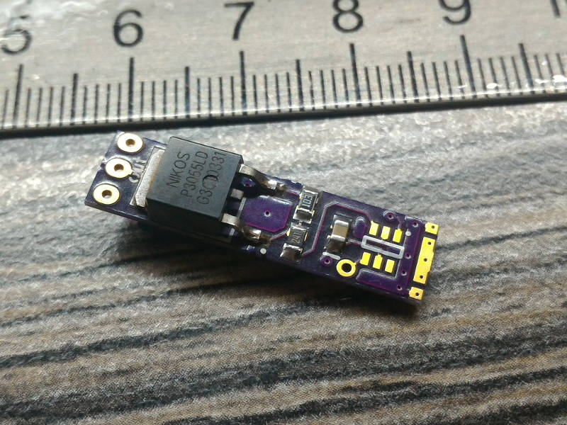
As the key -
P3055LD from the old motherboard
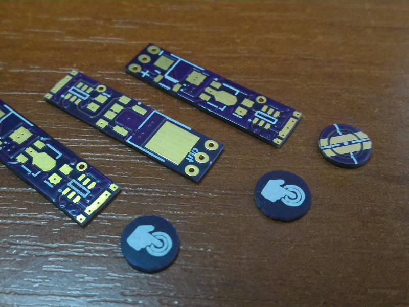
When designing a PCB, I proceeded from the fact that the holes in the end of the chipboard are minimally possible, I decided that a diameter of 7 mm would be enough. The board was 7x28mm, two layers. Ordered by
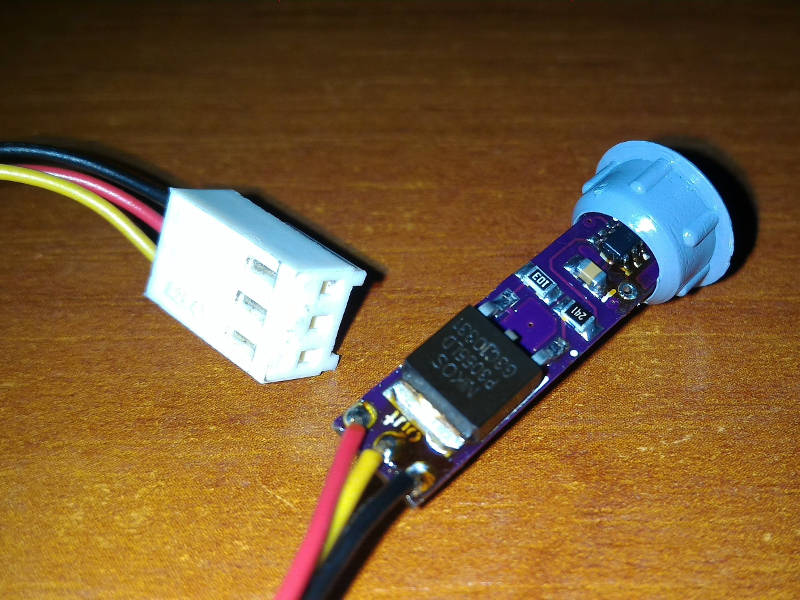
OSH ParkOnly then, when the board was soldered, it became clear that in the 7mm hole the board would not fit, at least 9mm - did not take into account the height of the elements. The idea with a sticker somehow stopped liking. And then I got a furniture stub! Designed for a 10mm hole, and the inside diameter is exactly 7mm! All coincided!
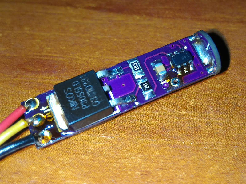
The very pencil of the sensor on a separate kerchief that is soldered to the main end. The pictures show
The control program is written in assembler. Every 32ms (Watchdog Timer) the sensor is interrogated. Depending on the current state and the duration of pressing, certain actions are performed. The logic of the work differs slightly from the prototype
Siemens S576BIf the light is off (status after power-up):
- A short press turns the lighting on the same level as it was turned off. When switched on for the first time at maximum brightness
- Long press to turn on the light at the maximum level
If the light is on:
- A short press turns off the lighting
- Long press changes the brightness. The direction of brightness change is changed by repeated long press
Too short pressing (interference) by the program is ignored. The brightness is set by the PWM ratio (13 bits). The PWM frequency is about 950 Hz
To compensate for the psychophysiological perception of the brightness of the lighting from the actual brightness, the change in the latter occurs over the section of the cubic parabola. Usually, tables are used for this, but in my version the coefficient is calculated. The coefficient varies with the frequency of the PWM, that is, when the brightness changes, each pulse is of its own duration. The minimum PWM value is limited programmatically
The main time MC sleeps and together with
TTP223 consumes about 16 microamps. That is, the scheme is quite suitable for devices with autonomous power supply
At
ATtiny4 six conclusions. Two on power, one by default to reset. I already used two. There was only one left. I thought how to use it. And then I remembered a new laptop of my friend with the Force Touch trackpad. As an experiment I decided to do something similar. I do not need special reliability of the response, and there are a lot of vibrators from old phones. As a result, I implemented a function in the program that a short pulse appears on the free terminal, when the adjustment limit is reached. In
Siemens S576B when the adjustment limit is reached, the direction of adjustment is changed. Therefore, it was necessary to have a certain skill that would remove the hand from the sensor at the maximum or minimum. In my implementation, when the boundary is reached, the adjustment stops. Total adjustment time from one border to another about 4 seconds
The code is available on
GitHubSeparately, I note the programming of MC. My
JTAGICE3 does not support the
TPI programming interface. But, fortunately,
good people wrote a sketch on Arduino for programming this trifle. Not at once, but I did it, the firmware was full and it all worked. In addition to arduiny need 4 resistors. The whole process is painted in a sketch
The magic button is installed and works as intended. Consumed current and dimensions allow it to be embedded in devices with autonomous power supply
I did not get the expected effect from the vibra. Here you probably need experiments with the installation site
In the prototype
Siemens S576B there is a conclusion
"Sleep". This is a mode in which the brightness falls very slowly until it turns off completely. According to the manufacturer, for this an additional sensor is installed near the head of the bed. 16 bits of the PWM timer enable this mode
This is from ideas for the future
Look like that's it
Thanks to all!


