Author Topic: LTZ1000 - nice die pictures  (Read 12385 times)

0 Members and 4 Guests are viewing this topic.

Online macboy

  • Super Contributor
  • ***
  • Posts: 2275
  • Country: ca
Re: LTZ1000 - nice die pictures
« Reply #25 on: February 04, 2020, 04:42:32 pm »

There is some similarity between LTZ1000 and LT1088. The isolations in the middle are the same, also the bondpads, the four transistors to measure the temperature and some metal structures. But the heaters are different, the buried zener and it´s transistor are missing completely...
It´s not completely different but they changed more than only the metal layer.
The heaters are made from the polysilicon layer, which is a deposited layer, similar to metal layers, not part of the crystalline silicon die. Also, there are clearly unused structures around the middle of the LT1088 which don't need to be there, but which are visually identical to useful structures on the LTZ1000. Is there any other explanation for their presence?
 

Offline NoopyTopic starter

  • Super Contributor
  • ***
  • Posts: 1825
  • Country: de
    • Richis-Lab
Re: LTZ1000 - nice die pictures
« Reply #26 on: February 04, 2020, 04:56:37 pm »

There is some similarity between LTZ1000 and LT1088. The isolations in the middle are the same, also the bondpads, the four transistors to measure the temperature and some metal structures. But the heaters are different, the buried zener and it´s transistor are missing completely...
It´s not completely different but they changed more than only the metal layer.
The heaters are made from the polysilicon layer, which is a deposited layer, similar to metal layers, not part of the crystalline silicon die. Also, there are clearly unused structures around the middle of the LT1088 which don't need to be there, but which are visually identical to useful structures on the LTZ1000. Is there any other explanation for their presence?

Are you sure the heaters are made from the polysilicon layer? Couldn´t it be possible that they are made with base- or emitter-doping?

The unused structures in the middle of the LT1088 are the isolation trenches (don´t know whether that´s really the right name for it) and you are right that are the same as in the LTZ1000.

I only wanted to say that they changed more than only the metal layer…

Offline iMo

  • Super Contributor
  • ***
  • Posts: 4896
  • Country: vc
Re: LTZ1000 - nice die pictures
« Reply #27 on: February 04, 2020, 05:10:57 pm »
You may doublecheck that based on the sheet resistance of the rings/heaters.
In 1088 the outer heater is 250ohm, made of 2x500ohm half_rings in parallel (low inductance).
Inner heater is 50ohm, made of 2x100ohm half_rings in parallel.

The LTZ outer heater is 300ohm = 2x600ohm full_rings in parallel, afaik.
« Last Edit: February 04, 2020, 05:23:07 pm by imo »
 

Offline NoopyTopic starter

  • Super Contributor
  • ***
  • Posts: 1825
  • Country: de
    • Richis-Lab
Re: LTZ1000 - nice die pictures
« Reply #28 on: February 04, 2020, 05:22:14 pm »
Let me explain why the difference is important for me anyway:

I found it very interesting that the LTZ1000 has two (four) unused heater rings beside the outer one (two) connected heater rings.
From that point on I gambled what they did with the unused heaters.
People say that the unused heaters are important for the LT1088 were they are used for the 50Ohm/250Ohm heaters. That would explain why there are two unconnected heaters in the LTZ1000.
Now that we have good pictures of the LT1088 we can say that the unused LTZ1000-heaters are no spare parts for the LT1088 and we come back to the interesting question why they have integrated These heaters.  :-/O

Addon:
Perhaps we have a misunderstanding regarding my sentence that the LT1088 doesn´t use the LTZ1000-die.
Of course they used the same ""base-material"" but they changed more than only the metal layer.
« Last Edit: February 04, 2020, 05:24:37 pm by Noopy »
 
The following users thanked this post: magic

Offline iMo

  • Super Contributor
  • ***
  • Posts: 4896
  • Country: vc
Re: LTZ1000 - nice die pictures
« Reply #29 on: February 04, 2020, 05:29:06 pm »
The 1088 and LTZ are absolutely different devices.
The 6 rings in LTZ have nothing to do with 1088, imho.
Based on the 1088 operation principle - a heater changing an input current into the heat (=rms), while sensing the heat with two diodes - they simply reused the design of LTZ as you "cannot do it better" (at that time they messed with it).
The 2 diodes in 1088 are made of those 4 symmetric transistors around the center (those 4 are in parallel).

PS: also the wiring of those heaters is different - see my above post. With 1088 you do need a low inductance of the heaters (you want to measure a high frequency AC rms), with LTZ you do not care.
« Last Edit: February 04, 2020, 05:46:56 pm by imo »
 
The following users thanked this post: Noopy

Offline NoopyTopic starter

  • Super Contributor
  • ***
  • Posts: 1825
  • Country: de
    • Richis-Lab
Re: LTZ1000 - nice die pictures
« Reply #30 on: February 04, 2020, 05:37:24 pm »
The 1088 and LTZ are absolutely different devices.
The 6 rings in LTZ have nothing to do with 1088, imho.
Based on the 1088 operation principle - a heater changing an input current into the heat (=rms), while sensing the heat with two diodes - they simply reused the design of LTZ as you "cannot do it better" (at that time they messed with it).
The 2 diodes in 1088 are made of those 4 symmetric transistors around the center (those 4 are in parallel).

Thanks!
That´s exactly what I thought.  :-+

Offline Kleinstein

  • Super Contributor
  • ***
  • Posts: 14474
  • Country: de
Re: LTZ1000 - nice die pictures
« Reply #31 on: February 04, 2020, 06:07:48 pm »
I see two possible reasons for the spare heaters:
One is that they had the LT1088 use in mind when they made the LTZ1000 masks and only later decided to make a separate LT1088.

Another point could be the control loop for the heater. The heater closer to the center could result in faster response and thus possibly a little simpler (smaller caps) control circuit. To this might have been an option to get easier control if really needed.  There is not much cost involved in having the extra heaters inside - the point that can add to the cost is the die size and thus the outer heater. So the inner rings could also have be there for a test if it may be possible to get away with a smaller (e.g. half the area) die using only the inner heaters. The LM399 run pretty hot for some reason. To run the LTZ1000 in the same temperature range would need quite some power so that the outer heater may need more than some 12 V. So a lower resistance heater (possibly using both) would help to operate at higher temperature without needed a higher voltage.  It turned out that high temperature operation is not desirable.

It is funny to also see some glowing around the buried zener.  AFFAIK the glowing is coming from hot electrons hitting the oxide and exiting higher energy states there - a little like writing to the EPROM.  This mechanism is supposed to be part of the high noise in conventional zeners. So the glowing should be highly undesirable as it likely is also causing noise and may cause aging too. My understanding of the buried zener was that it avoids the hot electrons at the surface.

Of cause it could be that the open LTZ1000 is one of the rare bad ones with high noise.
 

Offline NoopyTopic starter

  • Super Contributor
  • ***
  • Posts: 1825
  • Country: de
    • Richis-Lab
Re: LTZ1000 - nice die pictures
« Reply #32 on: February 04, 2020, 06:35:15 pm »
I see two possible reasons for the spare heaters:

Absolutely possible...  :-+


It is funny to also see some glowing around the buried zener.  AFFAIK the glowing is coming from hot electrons hitting the oxide and exiting higher energy states there - a little like writing to the EPROM.  This mechanism is supposed to be part of the high noise in conventional zeners. So the glowing should be highly undesirable as it likely is also causing noise and may cause aging too. My understanding of the buried zener was that it avoids the hot electrons at the surface.

Of cause it could be that the open LTZ1000 is one of the rare bad ones with high noise.

You mean the glowing in the LTZ1000-zener while there is flowing a current through it?
I only see glowing under the ring, where the buried zener border should be.
My explanation is second breakdown ionisation. I assume you mean the same with hot electrons. But that should not happen at the surface.

Offline NoopyTopic starter

  • Super Contributor
  • ***
  • Posts: 1825
  • Country: de
    • Richis-Lab
Re: LTZ1000 - nice die pictures
« Reply #33 on: February 07, 2020, 09:44:27 pm »
Hi all!

I wasn´t happy with the quality of my overview-picture of the LTZ1000.
So I have taken a new one:


Thanks to hotlinking the picture is also in the first post.  8)

By the way a picture of the die attachment:


https://www.richis-lab.de/

 
The following users thanked this post: SilverSolder

Offline TiN

  • Super Contributor
  • ***
  • Posts: 4543
  • Country: ua
    • xDevs.com
Re: LTZ1000 - nice die pictures
« Reply #34 on: February 08, 2020, 01:06:15 am »
Noopy, beauty.

Now you need to get LTZ1000A and photograph it's die attach with bubbles too.
YouTube | Metrology IRC Chat room | Let's share T&M documentation? Upload! No upload limits for firmwares, photos, files.
 

Offline SilverSolder

  • Super Contributor
  • ***
  • Posts: 6126
  • Country: 00
Re: LTZ1000 - nice die pictures
« Reply #35 on: February 08, 2020, 01:09:59 am »
Noopy, beauty.

Now you need to get LTZ1000A and photograph it's die attach with bubbles too.

Perhaps the bubbles are the cause of popcorn noise!   :-DD
 

Offline NoopyTopic starter

  • Super Contributor
  • ***
  • Posts: 1825
  • Country: de
    • Richis-Lab
Re: LTZ1000 - nice die pictures
« Reply #36 on: February 08, 2020, 08:28:26 am »
Noopy, beauty.

Now you need to get LTZ1000A and photograph it's die attach with bubbles too.

Thanks!  :-+

Definitely i need a LTZ1000A!  ;D I wonder if I´m able to capture the bubbles on a picture...

Offline NoopyTopic starter

  • Super Contributor
  • ***
  • Posts: 1825
  • Country: de
    • Richis-Lab
Re: LTZ1000 - nice die pictures
« Reply #37 on: June 23, 2020, 07:55:09 pm »
Good news:

I updated some pictures of the LTZ1000  8)

https://www.richis-lab.de/REF03.htm

Due to hotlinking the pictures in this thread are up to date.


Bad news:

I tried some more avalanche breakdown pictures. And... Well… The current limit was set to high...  :-\ :'(


R.I.P.

Offline SilverSolder

  • Super Contributor
  • ***
  • Posts: 6126
  • Country: 00
Re: LTZ1000 - nice die pictures
« Reply #38 on: June 23, 2020, 08:02:05 pm »

Well, that's one way to get it to emit light!  :D
 

Offline NoopyTopic starter

  • Super Contributor
  • ***
  • Posts: 1825
  • Country: de
    • Richis-Lab
Re: LTZ1000 - nice die pictures
« Reply #39 on: June 23, 2020, 08:07:55 pm »
Well, that's one way to get it to emit light!  :D

A bright light for a very short time.  8)

Offline NoopyTopic starter

  • Super Contributor
  • ***
  • Posts: 1825
  • Country: de
    • Richis-Lab
Re: LTZ1000 - nice die pictures
« Reply #40 on: December 14, 2020, 02:56:53 pm »
Now you need to get LTZ1000A and photograph it's die attach with bubbles too.

I still have no LTZ1000A but I have realized that my LT1088 has the same "air impregnated polymer"! So I took some more pictures of the LT1088:


The distance between the die and the package seems to be a little bit more than 100µm.
I meassured 28 bubbles. The average diameter was ~70µm. The diameter of the biggest bubbles is round about 100µm.

LT1088:
https://richis-lab.de/LT1088.htm
LTZ1000:
https://richis-lab.de/REF03.htm


 :-/O
 
The following users thanked this post: chuckb, RoGeorge

Offline doktor pyta

  • Frequent Contributor
  • **
  • Posts: 490
  • Country: pl
Re: LTZ1000 - nice die pictures
« Reply #41 on: December 14, 2020, 03:07:50 pm »
I'm answering question:

 
The following users thanked this post: SilverSolder, Gyro, chuckb, Hydron

Offline NoopyTopic starter

  • Super Contributor
  • ***
  • Posts: 1825
  • Country: de
    • Richis-Lab
Re: LTZ1000 - nice die pictures
« Reply #42 on: December 14, 2020, 03:09:35 pm »

Offline coromonadalix

  • Super Contributor
  • ***
  • Posts: 6224
  • Country: ca
Re: LTZ1000 - nice die pictures
« Reply #43 on: December 14, 2020, 03:55:00 pm »
One thing i'm curious about :   for parts like this, or put in a metal can,   do they vaccum the air out ?!
 

Offline NoopyTopic starter

  • Super Contributor
  • ***
  • Posts: 1825
  • Country: de
    • Richis-Lab
Re: LTZ1000 - nice die pictures
« Reply #44 on: December 14, 2020, 04:37:57 pm »
One thing i'm curious about :   for parts like this, or put in a metal can,   do they vaccum the air out ?!

I don´t know.  :-//
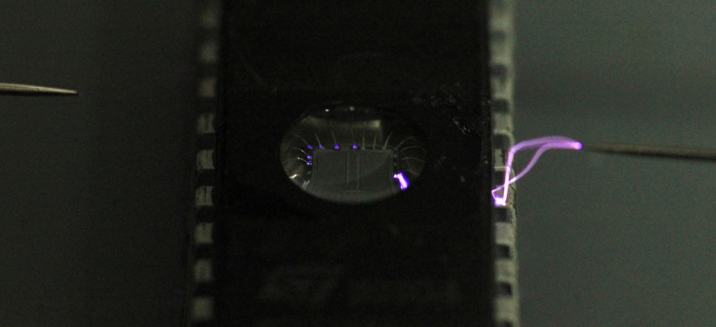
High voltage says UV-EPROMs are placed in a vacuum (or at least low pressure):


https://richis-lab.de/hv-mixed_2.htm

 ;D
 
The following users thanked this post: RoGeorge

Offline bson

  • Supporter
  • ****
  • Posts: 2313
  • Country: us
Re: LTZ1000 - nice die pictures
« Reply #45 on: December 14, 2020, 11:07:46 pm »
I wonder if those unused ring traces could potentially be used for guard currents, to reduce noise pickup from the heater traces?
 

Offline RoGeorge

  • Super Contributor
  • ***
  • Posts: 6462
  • Country: ro
Re: LTZ1000 - nice die pictures
« Reply #46 on: December 15, 2020, 12:00:30 am »
High voltage says UV-EPROMs are placed in a vacuum (or at least low pressure):


https://richis-lab.de/hv-mixed_2.htm

 ;D

Wow, very interesting!
I didn't know that.   :o

From your blog, you were using 20kV, but I assume most of the voltage drop will be across the length of the two sparks, therefore the voltage between the Vcc and the address pin 4 of the EPROM must have been much lower than 20kV.


Have you tried doing that with direct contact and much lower voltage?  I wonder what would be the minimum voltage that can still make the wire glow.  Also, was the negative pole of the 20kV on the left side (pin 4)?

Does the whole chip lights up instead of just the bonding wire if the polarity is reversed?
« Last Edit: December 15, 2020, 12:03:15 am by RoGeorge »
 

Offline NoopyTopic starter

  • Super Contributor
  • ***
  • Posts: 1825
  • Country: de
    • Richis-Lab
Re: LTZ1000 - nice die pictures
« Reply #47 on: December 15, 2020, 04:44:00 am »
I wonder if those unused ring traces could potentially be used for guard currents, to reduce noise pickup from the heater traces?

That´s at least possible...  :-//


I didn't know that.   :o

Well that´s not a standard testcase.  ;D


From your blog, you were using 20kV, but I assume most of the voltage drop will be across the length of the two sparks, therefore the voltage between the Vcc and the address pin 4 of the EPROM must have been much lower than 20kV.

Yes, the voltage across the EPROM was lower than 20kV.
How much... Don´t know...  :-//


Have you tried doing that with direct contact and much lower voltage?  I wonder what would be the minimum voltage that can still make the wire glow.  Also, was the negative pole of the 20kV on the left side (pin 4)?

No, didn´t try that. The Heinzinger supply can do lower voltages. I have never tried that but should be possible. Taking such pictures isn´t easy because of the timing but I can try to take some more with different voltages.
I´m not sure where the negative pole was, sorry.  :-//


Does the whole chip lights up instead of just the bonding wire if the polarity is reversed?

I didn´t zap special pins. I just took the pins near to my electrode.

I uploaded two more pictures:
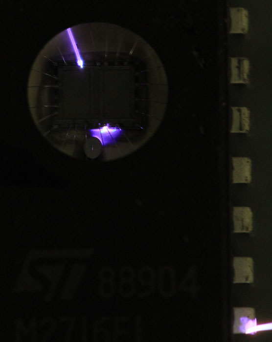


With 20kV the ESD-pad is enough to conduct the high voltage...  ;D
Here the positive high voltage has to be on the right side.

 :-/O
 
The following users thanked this post: RoGeorge


Share me

Digg  Facebook  SlashDot  Delicious  Technorati  Twitter  Google  Yahoo
Smf