Author Topic: How to detect actuator feedback voltage using Arduino/esp32?  (Read 746 times)

0 Members and 1 Guest are viewing this topic.

Offline mrnamsTopic starter

  • Newbie
  • Posts: 5
  • Country: in
    • MrNams
How to detect actuator feedback voltage using Arduino/esp32?
« on: September 21, 2023, 02:39:46 pm »
Hello,
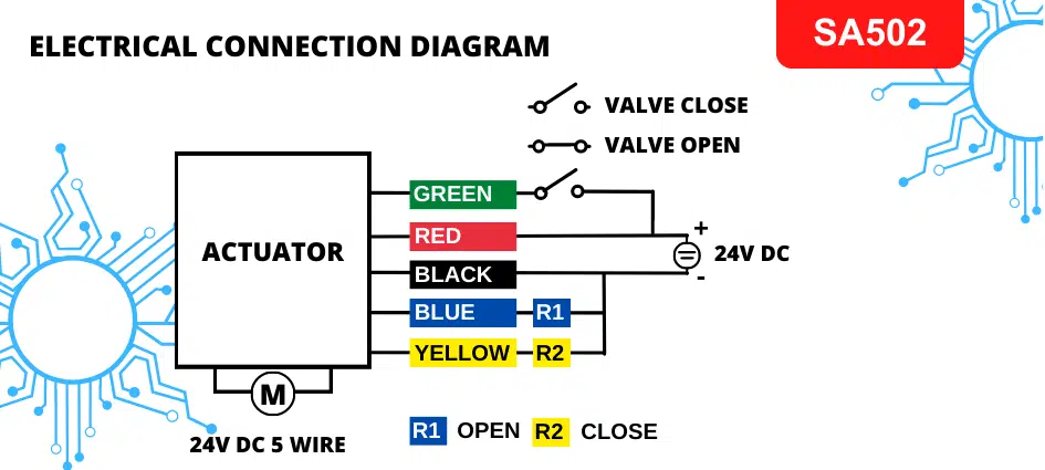
I am operating motorized ball valve using ESP32 and relay module, ball valve has two feedback voltage to detect close and open position of valve, there are two output wires one to detect close state and one to detect open state of valve. see below image.

My question is how to collect feedback using Arduino/ESP32 to detect open/close state of valve ?
Open state voltage between "R1(BLUE) and Negative(BLACK) will be 24v DC
Close state voltage between "R2(YELLOW) and Negative(BLACK) will be 24v DC
 

Offline jwet

  • Frequent Contributor
  • **
  • Posts: 534
  • Country: us
Re: How to detect actuator feedback voltage using Arduino/esp32?
« Reply #1 on: September 25, 2023, 03:46:04 am »
The blue and yellow wires tell the state of valves except that they're 24v rather than the 3.3v you need.  Connect a voltage divider to blue and yellow that is 100k on the top and a 10k on the bottom going to black.  Take your output from the junction of the two R's to the ESP.    This a 11 to 1 divider and will safely give you a logic high when there is 20-30v (24v nominal) on these lines.  Before connecting ESP, use a voltmeter to verify that you don't have a wiring error and you get either 0v or >2.4v in the two valve states.


Share me

Digg  Facebook  SlashDot  Delicious  Technorati  Twitter  Google  Yahoo
Smf