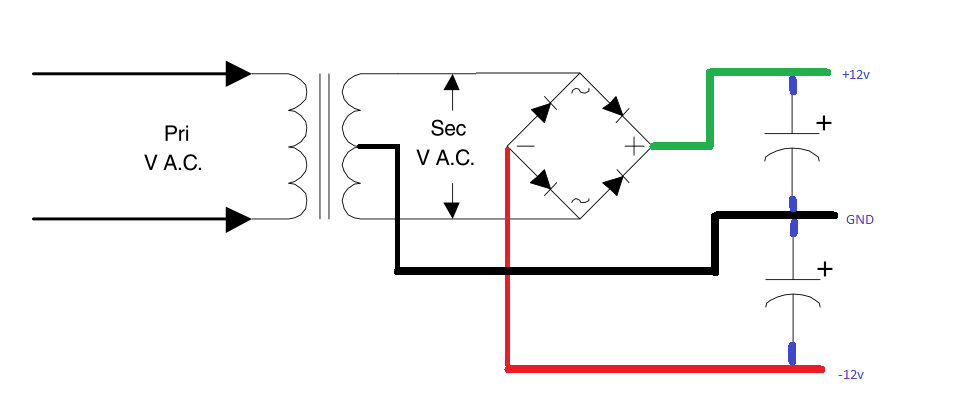
If you want to make -12v and +12v, you can use this :

On the + side, you can use 7812, on the - side, you can use 7912
Like c4757p says above, the transformer is 24v RMS , or 12v - 0v - 12v rms ... that means the peak voltage on both sides is 1.41 x 12v = 16.92v. Then the voltage drop of each diode working at one time for each AC pulse has to be taken off, so you're left with about 16.3-16.5v.
But that 17v is the peak voltage, the average is less, so you have to use those capacitors that get charged while the transformer gets close to the peak voltage and then as the sine wave goes down, the capacitor can provide energy and smooth out the DC output.
I've written the formula to compute the proper size of the capacitor a few posts above. Capacitance = [ Current x Duty Cycle Capacitor ] / [Vripple x Frequency ]
Current is how much you want to pull from the transformer, let's say 1 A for this example.
Duty cycle is an estimated value, about how much time the capacitor has to provide power in contrast with how much time it can charge. a value of 70% (0.7) is reasonable.
V ripple is how much you're willing to let that voltage go down, in volts... Since you want the voltage to go down as low as 12v + 2v (you say 1.5v but 2v is safer) that means we can use 16.3v - 14.5 v = 1.8v here. But let's be on the safe side and say a maximum of 1.5v
Frequency is how many pulses of power come from the transformer and rectifier diodes.
If you're in US, the AC frequency is 60 Hz. If you're in Europe, the frequency is 50 Hz.
The way the diodes are layed out in the above circuit, it makes it that the cycles double, so if you're in US the frequency is 120 Hz, if you're in Europe the frequency is 100 Hz.
So now the formula becomes : Capacitance = 1 x 0.7 / (1.5 x 120) = 0.7 / 180 = 0.003888 F (I'm assuming you're in US, so I used 120Hz)
That's 3888 uF, so you'd have to use at least something above 3900 uF to have at most 1.5v ripple after the capacitors and keep the 7812 happy. I would use 2x2200uF or 2x3300uF - the more the better but don't overdo it, it's not worth having more than 10000uF in this case.
Looks like I'm contradicting David_AVD a bit, but I may also be wrong. Make the circuit on the breadboard and see!
later edit: And I think it should be fairly obvious the capacitors should be rated for 25v or more, since your peak voltages will be over 16v... If you use 16v capacitors they may vent or pop, be careful!
(if you only have 16v caps at hand, put 1 or 2 diodes before the capacitor, in series... each diode will drop 0.4-0.7v so you'll have under 16v on the capacitor)