This could be made somewhat more compact, using a 2x4 header (which has 10 distinct positions where a jumper can be plugged) and 6 resistors (of two values) per decade.
One downside to this layout is that you cannot short the '9' position to keep the resistance finite when moving a jumper - that would result in an incorrect resistance in some positions due to resistors ending up in parallel.
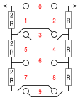
Inspired by the above post, I did some more thinking, and came up with a
slight improvement (I think).

In case the improvement is not apparent, it's the fact that the altered resistor order means that the jumpers now proceed down the pin field in consistent increments of 3 per level, rather than switching from side to side. This may simplify the annotation. Or it may not, as the previous arrangement has only odd numbers one side, and evens the other.
I also take issue with Jason's assertion that you cannot leave '9' shorted. Any lower numbered jumper shorts the resistors leading up to node '9', meaning that node 9 has no effect on lower valued jumper positions. Leaving the 9 link shorted has two benefits. It eliminates one layout crossover. It means removing a jumper never gives an open circuit, required in many applications.
As well as these 6 resistor solutions, there are also two 4 resistor networks that can be shorted by a single link to yield all resistance values from 0 to 9, (1,3,3,2) and (1,1,4,3). However these do not share the elegant pin locations and easy jumpering of these 6 resistor solutions, or indeed the 9/10 resistor solution that is the subject of this thread.


