-
Hello all
 I'm currently in a little bit of a pickle and need a little help. I have been tasked by my Uncle and my Dad to design some replacement LED indicators for their vintage car. The main problem I think I have is the lack of skills in LED light driving.
The car is an old 1920s (?) Essex that has a 6v electrical system. So I'm thinking of using a cheap LM317 as a CC source powering 2 x 39lm LEDs (Cree XLamp ML-E MLEAWT-A1-R250-0002E7 http://au.element14.com/cree/mleawt-a1-r250-0002e7/high-brightness-led-warm-white/dp/1855586) in parallel.
Now the questions I have for the forum are:
1. Would these LED's be adequate for an indicator lamp?
2. Does the LM317 CC source follow voltage? as example, I might design this for a 6v system, but what design aspects would come into play if he decides to upgrade to a 12v system? -
Just use a proper led driver, like this one for example:
http://uk.farnell.com/micrel-semiconductor/mic2287cyd5-tr/pwm-wled-driver-1-2mhz-sot23-5/dp/1663103RL
2.5-10v input , up to 500mA output current ... just put two white leds in series and this controller will have no problems doing 150mA or whatever current you want to set. Read the datasheet, it's easy...
or if you want cheaper (less external parts), one bcr320u/bcr321u for each led (or put the two leds in parallel)... these parts can do up to 250mA :
http://uk.farnell.com/infineon/bcr321u/ic-led-driver-0-5w-leds-6sc74/dp/1791066RL
http://uk.farnell.com/infineon/bcr320u/ic-led-driver-0-5w-leds-6sc74/dp/1791065RL
-
Thanks mariush
So I should find a LED driver for the 12v or so (if he was to upgrade) and since the LEDs are 4 pole (2 leds in 1 package) should I run all of the leds in series (like configure the LED for series and then put them both in series OR should I put the LED in parallel mode and then run them in series? -
I didn't check the datasheet for those leds, I just looked at the description on the page and noticed forward voltage = 3.2v and current = 150mA.
If you want to make everything compatible with 12v, the first chip (mic2287) is out. That chip is designed to use a low voltage (2.5-10v with an absolute maximum of 12v which won't work for you, because a 12v car battery may give you up to 14v and would damage the chip).
The chip would then boost the voltage as much as needed until the current going through the led(s) on the output reaches the amount you set. The idea would be to configure the chip to 150mA, you would set two leds with 3.2v in series on the output (so you'd have a 6.4v 150mA led) and then the chip would boost the 6v input voltage to 6.4v and light up the leds.
This chip only works in boost mode, so it's not easy to use such chip to light up just a couple of leds that don't need so much voltage.
The other two chips (bcr320/321) are however designed differently... you power the leds directly from the input voltage and after the leds you put this chip and the chip will only let a particular amount of current to the ground.
So with such chip, it doesn't matter if the input voltage is 6v or 12v (the chip supports up to 25v input voltage), you just put one or more leds in series and then after the leds you put this chip and configure it to only let 150mA (or whatever value you want) go through.
Naturally, with this chip, the input voltage must be higher than the voltage dropped on the leds and the chip itself ... so you can't use a 6v input voltage and put two leds in series (as these would need 6.4v to light up).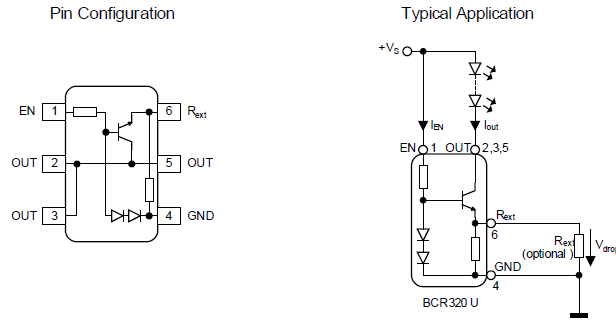
The led you linked has the leds connected in parallel , so you have a forward voltage of 3.2v and max current of 150mA ... so in the picture above you just have to have the input voltage higher than 3.2v and the resistor near the chip to about 5-6 ohm (which gives you 150mA):
Note that there's some other gotchas you can deduct from the graphs in the datasheet, like the chip is only capable of 100mA when you give it at least 5v... but in your case, it's not an issue, you're gonna have at least 6 volts.
That's pretty much it... at least I think I got it right and I'm not writing something stupid.. it's 8 am here and I didn't sleep this night so I may be missing something obvious or making some mistake. -
Are you talking about LED replacements for exterior indicators or on the dash? I'm assuming turn signals here, but wondering if your terminology is a little different, because a 1920s car would not have OEM turn signals.
-
@mariush Would the Panasonic AN30888A-VF (found here http://au.element14.com/panasonic/an30888a-vf/led-driver-boost-buck-buck-boost/dp/2291453) be a better choice being a 3v to 20v input voltage driver?
@Six_Shooter they are external turning signals and I'm only guessing that its 1920s
-
This is actually very easy to do with only LEDs and a resistor (or few) per light. Running a pair in series and adding a current limit resistor will do the job. Better yet using 4 or 6 in a series/parallel to have more light will work just as well.
If you take after some of the LED replacement lights that are made for tractor trailers, they use a small inductor to provide an inductive load that will work with conventional flasher units. -
The problem is when and if my uncle upgrades the car from a 6v to a 12v system and since a lamp designed for a 6v system would burn out on a 12v system because everything increases (or decreases) as a ratio.
Even if I chose to use 12v replacement bulbs they probably wont work (or would be super dull) on a 6v system so I'm trying to make his life as simple as I can by designing my lamp for 6v to 12v (basically 5v to 15v taking in account a flat battery on a 6v system and the system voltage of a running 12v system).
Good idea though Six_Shooter but it would only really work on one system not both. -
I didn't check the datasheet for those leds, I just looked at the description on the page and noticed forward voltage = 3.2v and current = 150mA.
How about adding a buck converter to give 5V before the circuit?
If you want to make everything compatible with 12v, the first chip (mic2287) is out. That chip is designed to use a low voltage (2.5-10v with an absolute maximum of 12v which won't work for you, because a 12v car battery may give you up to 14v and would damage the chip).
The chip would then boost the voltage as much as needed until the current going through the led(s) on the output reaches the amount you set. The idea would be to configure the chip to 150mA, you would set two leds with 3.2v in series on the output (so you'd have a 6.4v 150mA led) and then the chip would boost the 6v input voltage to 6.4v and light up the leds.
This chip only works in boost mode, so it's not easy to use such chip to light up just a couple of leds that don't need so much voltage.QuoteThe other two chips (bcr320/321) are however designed differently... you power the leds directly from the input voltage and after the leds you put this chip and the chip will only let a particular amount of current to the ground.
I love the simplicity of that IC. Not very modern ICs are as basic as something you can build from a single transistor and a couple of resistors and diodes.
So with such chip, it doesn't matter if the input voltage is 6v or 12v (the chip supports up to 25v input voltage), you just put one or more leds in series and then after the leds you put this chip and configure it to only let 150mA (or whatever value you want) go through.QuoteNaturally, with this chip, the input voltage must be higher than the voltage dropped on the leds and the chip itself ... so you can't use a 6v input voltage and put two leds in series (as these would need 6.4v to light up).
I agree with two LEDs on the output you won't get the rated output current with 6V in but it won't abruptly stop working. It'll be dimmer but may still be usable depending on the type of LEDs used. A 6V system will typically run at 7V with the engine running and 6.3V when stopped so it may be acceptable. -
Quote
1. Would these LED's be adequate for an indicator lamp?
You probably have to try.Quote2. Does the LM317 CC source follow voltage?
A LM317 would be more than enough, and I would use 1 lm317 to drive each of the leds - just to be safe.Quoteas example, I might design this for a 6v system, but what design aspects would come into play if he decides to upgrade to a 12v system?
You will need to consider the power dissipation on the LM317 (and the resistors, to a lesser extent). Assuming that you run the leds at 100ma per led - very bright, in my view. At 6v, the power dissipation on the LM317 would be (6-3.2)*0.1 = 0.3w - not a big problem, even with a small heatsink.
At 12v, the power dissipation on the LM317 is (12-3.2)*0.1 = ~1w -> you have to use a fairly reasonable heatsink here.
The power dissipation on the current-setting resistor will be 1.2v * 0.1a = 0.1w -> I would use a 1/4w or 1/2w resistor here.
-
Wouldn't six_shooter's solution be cheap enough to just wire for 6v and 12v, and tell your uncle not to forget to flip a switch over when he upgrades?
-
what I might do is make a led tester just to see how bright the leds I chose actually are.
4 AA batteries, a CC source (just to make sure I don't burn the cheap led out) and a way to hook up the led to the circuit.. maybe some leads and alligator clips.
Thanks for the help so far guys
-
Why would you want to use the MLE-AWT white LED for a turn signal? I am assuming you use yellow turn signals in Oz? Using a white LED behind a yellow lens is a bad idea - it is very inefficient, all you are doing is generating white light and then blocking almost all of that light except a narrow band of the yellow range.
You would be better to use a yellow LED from the get go. Something like a Cree XBDAMB LED or a Lumilds LXM2-PL01 LED.
Second, if you want something that will run on 6V or 12V, I would probably determine how likely the switch to 12v really is. I manufacture automotive electronics and everyone with a 6V system has a plan to move to 12V. But what is the point of upgrading to LED's shortly before moving to a 12V setup? I don't see the point of that... he should either stick with the 6V or upgrade to 12V then move to LED's. It sort of sounds like a case of "design gone wild" where every possible outcome is being accounted for - but designing for 6V and 12V just so it works for 6V for a short period of time is needlessly complex, especially for an aftermarket replacement that is being done by choice and not out of necessity.
Having said that, if the 6V/12V thing is really necessary, I would design for 12V and make a 6V->12V boost module that you put inline while he is still running on 6V. There are just too many differences between 6V and 12V to make an LED system that runs on both without serious compromises.
As for the LED's themselves... you can't test them with some AA batteries, even with a constant current setup. Any surface mount LED that runs above around 20mA uses the copper pads on the PCB for heat sinking - that incudes the Cree ML-E. If you solder wires to the LED directly, it will overheat in a matter of seconds when you run it at 150mA. To see its brightness, you really need to solder it to a PCB with large copper pours and appropriate heat sinking.
I would say that even if you used the amber version of the Cree ML-E, two of them is seriously inadequate for a turn signal. You should be shooting for at least 200-300 lumens per signal of amber light (not white) minimum. I would go for 3 or 4 Cree XB-D's running at 350mA at a minimum, or maybe 10 ML-E's in amber running at 100mA or so. It's not really the best idea to run LED's at full current because they are much less efficient there - you can do it if you really need max brightness, but in a hobby project like yours where cost and size are likely not a huge issue, you should be more concerned with heat and longevity and err on the conservative side.
As for the LED driver, look at the AP8803 from Diodes Inc. Super easy to use, wide Vin range, cheap, very reliable, etc. Make sure you put plenty of capacitance on the input, and a TVS at least for load dumps and transients. -
I recently talked to my uncle and he isn't planning to upgrade which makes my life easier.
We do use amber/orange turning signals here in Australia, and the housing has an orange lens so I thought either white or amber/orange would do.
I have next to no experience in lighting so I looked up some information, I saw that there was already a 12v 3W globe in the housing and what I saw from a google search was 16lm/W for an incandescent globe (48lm) so I worked off that :/ I was obviously incorrect
So I'm going to have to aim for 200-300 lumen in orange/amber light with good thermal design.
Could I put an inductor on the input to "simulate" the effects of a incandescent so he wont need to change his blinker can?
Thanks for the pointers Corporate666 -
I'd be tempted to use relays controlled by the 6V system that switch off and on 12V lights. Though once you get to this point you have to figure out how to keep the 12V system charged.
What if we went about this from the other direction. Replace the generator / magneto (if not part of the engine) with a modern alternator and automotive regulator that charges 2 6V batteries in series. Use the full 12V for the lighting and tap off one of the batteries for 6V. Or use a standard automotive 12V battery with a high current 6V regulator. -
I recently talked to my uncle and he isn't planning to upgrade which makes my life easier.
We do use amber/orange turning signals here in Australia, and the housing has an orange lens so I thought either white or amber/orange would do.
I have next to no experience in lighting so I looked up some information, I saw that there was already a 12v 3W globe in the housing and what I saw from a google search was 16lm/W for an incandescent globe (48lm) so I worked off that :/ I was obviously incorrect
So I'm going to have to aim for 200-300 lumen in orange/amber light with good thermal design.
Could I put an inductor on the input to "simulate" the effects of a incandescent so he wont need to change his blinker can?
Thanks for the pointers Corporate666
Is the move to LED's for extra brightness? Or reduced power draw? Or for the novelty of LED? Or all of the above?
I am surprised the existing bulbs are only 3W - most blinkers in cars here use 1156 or 1157 bulbs which are 25W. If you are concerned about power draw, you could stick with the existing 3W draw, but the most efficient yellow LED's will get maybe 90 lumens per watt, so you would be lucky to get 250 lumens considering driver inefficiency, but that would be MUCH brighter than an existing 3W bulb, especially if the existing bulb is white (since it makes white light but most of that light is blocked by the yellow lens).
So if you are going with the 6V system, I like the MLE LED's since they are still pretty efficient... the higher bins can achieve 90 lumens/watt at 150mA. I don't know how comfortable you are using surface mount parts, but a quick look at Digikey, and I would probably consider something like the Texas Instruments TL4242 boost LED driver. -
I'd be tempted to use relays controlled by the 6V system that switch off and on 12V lights. Though once you get to this point you have to figure out how to keep the 12V system charged.
What if we went about this from the other direction. Replace the generator / magneto (if not part of the engine) with a modern alternator and automotive regulator that charges 2 6V batteries in series. Use the full 12V for the lighting and tap off one of the batteries for 6V. Or use a standard automotive 12V battery with a high current 6V regulator.
Why complicate matters?
The 6V lighting would be pretty easy to deal with.
The idea of using 2 6V batteries in series in a 6V vehicle has been used for many, many years, there are some compromises to the system though. The biggest benefit to doing that set-up is engine cranking. You use the 12V output of the batteries for starter motor, and run the rest of the car off the second battery (the one that has the direct connection to the chassis). -
Is the move to LED's for extra brightness? Or reduced power draw? Or for the novelty of LED? Or all of the above?
I am surprised the existing bulbs are only 3W - most blinkers in cars here use 1156 or 1157 bulbs which are 25W. If you are concerned about power draw, you could stick with the existing 3W draw, but the most efficient yellow LED's will get maybe 90 lumens per watt, so you would be lucky to get 250 lumens considering driver inefficiency, but that would be MUCH brighter than an existing 3W bulb, especially if the existing bulb is white (since it makes white light but most of that light is blocked by the yellow lens).
So if you are going with the 6V system, I like the MLE LED's since they are still pretty efficient... the higher bins can achieve 90 lumens/watt at 150mA. I don't know how comfortable you are using surface mount parts, but a quick look at Digikey, and I would probably consider something like the Texas Instruments TL4242 boost LED driver.
The move is because its an old bayonet style lamp, and being able to find new replacement bulbs locally is hard. So, I suggested LEDs because they are more efficient and they last longer (especially when used at currents lower then their limit).
2 photos of the housing below
https://www.dropbox.com/s/g8yu9ll9tdwd9vc/2013-11-30%2012.54.45.jpg
https://www.dropbox.com/s/1nu144bjnom1yo4/2013-11-30%2012.55.10.jpg
I was going to design the board in such a way where the "heatsink tracks" would make their way to the mounting point on the housing, so that would help with the thermals a bit considering there would be fresh air flowing over the housing when the car is in motion. -
As I suspected those are add-ons at a much later date, likely due to legislation requiring all cars to have them. I know what some of you Aussie's go through to get your cars on the road, especially older and modified cars. I'm glad I don't have to deal with that.
I'm going to STRONGLY suggest keeping this simple, I would forget about LED drivers or any active circuitry, it's simply not needed. You won't need to worry about any thermal conductance or provisions. I've also seen many LED conversion systems available that use active circuitry (such as the sequential tail light conversions) that fail in short time, for various reasons.
The other thing to consider is that IF your family member ever does swap to a 12 volt charging system, modifying or replacing the LED conversion you are doing now will be the least of his worries, there's so many other components that will need changing that, these would just be one small part of the check list.
Have you considered how you're going to get the turn signal flasher to function? Most flashers use the load of the bulbs on to heat up a bi-metal contact and is what causes the flasher to actually function. This is where a small inductor placed in parallel with the circuit is sometimes needed as I mentioned previously. You can get flashers for LED systems and for combination LED/conventional bulb systems as well.
Many times the simplest solution is the best. -
I'm going to STRONGLY suggest keeping this simple, I would forget about LED drivers or any active circuitry, it's simply not needed.
In general, I have to disagree with this....
Consider a standard 12V system. Many people say "just pick the right value resistor and away you go".
Ok, so let's say you have an LED with a forward voltage of 2.4V and If of 100mA. A car electrical system can vary from maybe 10.4 volts when off to 14.5 volts when running. So if you wanted to run a string of 4 LED's... what resistor value do you choose?
4 LED's is Vf of 9.6, so let's say you choose an 8 ohm resistor. At your lowest voltage, you are getting 100mA and things are good. But when you turn on the ignition and the voltage goes to 14.5, now your LED's are running at 600mA and they blow up. If you choose your resistor value based on your maximum voltage of 15, that would be say 54 ohms for 100mA for your 9.6 forward voltage LED string. But now at 10.4 volts, you're only getting 15mA through your LED's... when you start the engine and the voltage rises to 14.5V, now 90mA is flowing through your LED's. That is a very big difference and will be very noticeable - it will make the LED's look much brighter when the engine is running.
Now I realize you were not suggesting he just use a simple resistor, but in case you were, I have to say I disagree with that.
And when you consider that a chip like an RT8472 is $0.25 and needs only a capacitor, diode and inductor to run and is constant current and offers PWM of voltage level dimming, I think there's little reason to go with that solution. Total parts cost is something like $0.65 exclusive of the LED, probably equal or cheaper than any linear solution, plus you get dimming and it's a switcher so much more efficient and less heat - and heat is always an issue with higher power LED's anyway, so there's no sense in making the heat issue even worse by burning power as heat with a linear solution.
Active solutions are super simple, cheap and easy to implement. Plus it's the right way to drive LED's. There's no reason not to do it that way other than fear of the unknown, IMO. -
I'm going to STRONGLY suggest keeping this simple, I would forget about LED drivers or any active circuitry, it's simply not needed.
In general, I have to disagree with this....
Consider a standard 12V system. Many people say "just pick the right value resistor and away you go".
Ok, so let's say you have an LED with a forward voltage of 2.4V and If of 100mA. A car electrical system can vary from maybe 10.4 volts when off to 14.5 volts when running. So if you wanted to run a string of 4 LED's... what resistor value do you choose?
4 LED's is Vf of 9.6, so let's say you choose an 8 ohm resistor. At your lowest voltage, you are getting 100mA and things are good. But when you turn on the ignition and the voltage goes to 14.5, now your LED's are running at 600mA and they blow up. If you choose your resistor value based on your maximum voltage of 15, that would be say 54 ohms for 100mA for your 9.6 forward voltage LED string. But now at 10.4 volts, you're only getting 15mA through your LED's... when you start the engine and the voltage rises to 14.5V, now 90mA is flowing through your LED's. That is a very big difference and will be very noticeable - it will make the LED's look much brighter when the engine is running.
Now I realize you were not suggesting he just use a simple resistor, but in case you were, I have to say I disagree with that.
And when you consider that a chip like an RT8472 is $0.25 and needs only a capacitor, diode and inductor to run and is constant current and offers PWM of voltage level dimming, I think there's little reason to go with that solution. Total parts cost is something like $0.65 exclusive of the LED, probably equal or cheaper than any linear solution, plus you get dimming and it's a switcher so much more efficient and less heat - and heat is always an issue with higher power LED's anyway, so there's no sense in making the heat issue even worse by burning power as heat with a linear solution.
Active solutions are super simple, cheap and easy to implement. Plus it's the right way to drive LED's. There's no reason not to do it that way other than fear of the unknown, IMO.
Considering I've done this on MULTIPLE occasions, I know it works EXTREMELY well. You can do all of the math you want, but in practice the intensity of the LEDs varies little between engine off and running, most people would not notice the difference. If your 12V battery is resting at 10.4 volts it's dead and you need to replace it. A 12V car battery should rest at 12.6V fully charged with no load. In practice it will usually sit about 12.4 to 12.5 due to some parasitic drain for some of the on board electronics, and should never go over 14.4 volts when charging. If the voltage goes higher then the regulator is shot failing or failed and needs to be replaced. But we are talking about a 6V system here., resting voltage should be around 6.3 volts and should not reach much beyond 8 volts when charging, if it ever gets that high, I know my Grandfather's 40 Dodge that has a 6V system barely gets that high.
You want dimming? Add a resistor and diode to the circuit to give dual brightness for running light and turn signal. You really need to look at the available LED replacement lights on the market, very few, if any actually use anything more than a resistor or two and sometimes an inductor (to simulate load), that I have used or seen.
"The right way" is subjective, since a correct way to have this work is to simply use a resistor that will limit current based on maximum voltage the system will attain, works very well as I have said. -
I would honestly feel better and safer using a constant current source. Knowing the LEDs are running at the right voltage and current would make me more comfortable
-
Considering I've done this on MULTIPLE occasions, I know it works EXTREMELY well. You can do all of the math you want, but in practice the intensity of the LEDs varies little between engine off and running, most people would not notice the difference. If your 12V battery is resting at 10.4 volts it's dead and you need to replace it. A 12V car battery should rest at 12.6V fully charged with no load. In practice it will usually sit about 12.4 to 12.5 due to some parasitic drain for some of the on board electronics, and should never go over 14.4 volts when charging. If the voltage goes higher then the regulator is shot failing or failed and needs to be replaced. But we are talking about a 6V system here., resting voltage should be around 6.3 volts and should not reach much beyond 8 volts when charging, if it ever gets that high, I know my Grandfather's 40 Dodge that has a 6V system barely gets that high.
You want dimming? Add a resistor and diode to the circuit to give dual brightness for running light and turn signal. You really need to look at the available LED replacement lights on the market, very few, if any actually use anything more than a resistor or two and sometimes an inductor (to simulate load), that I have used or seen.
"The right way" is subjective, since a correct way to have this work is to simply use a resistor that will limit current based on maximum voltage the system will attain, works very well as I have said.
Well, there is a reason not a single OEM has ever used a simple resistor on an unregulated LED on any automotive application in the history of automotive applications - because it's shit design - period. There are lots of people who build unfused stuff that they run on mains and say it runs "fine", but that doesn't mean it's good design. And it's indisputable that adding heat to a system where you are trying to manage heat is a bad idea.
When you are using LED's that require a custom PCB anyway because they use the PCB tracks for heat dissipation, there is really zero reason not to use the correct approach other than not being knowledgeable in the right way to do it. But it's not hard to do or expensive to do, so may as well do it the right way. It's more electrically efficient, it's more thermally efficient, it will make the LED's last longer, it will simplify thermal design and it's the reason LED drivers exist in the first place.
When you are trying to be efficient and string LED's together to get a more reasonable Vf, it's even more important.
The right way really isn't subjective. The SAE in the USA publishes documents which state the standards which should be met, and each country has their own. That doesn't mean the hobbyist needs to stick to the letter of the standard, but flaunting them with known shoddy design is a bad idea as well, especially when good design is so easy and trivial in comparison.
I think you really need to look at what the reputable manufacturers like Koito, Stanley, Sylvania and such are manufacturing. I've opened up hundreds OEM LED headlights, tail lights and turn signals and I have never seen a single one that uses just a resistor right off 12V. -
SO... Just so I get things straight...
That RT8472 could run 2 x 2.5v 350mA Cree XP-C LEDs from a 6v source without issues?
My Current BOM (Feel free to criticize it)
6 x Cree Amber XP-C LEDs (XPCAMB-L1-R250-00401)
3 x Richtek RT8472
Total estimated lumen output at 350mA/LED is 330lm
(Passive components to suit)
Also, how would I calculate total current draw? I realize it'll be bugger all but it would be useful for correct fusing for the circuit -
I've opened up hundreds OEM LED headlights, tail lights and turn signals .....
Hundreds !!
Just curious how many 12 volt based led lights you've built ?