I wonder if those unused ring traces could potentially be used for guard currents, to reduce noise pickup from the heater traces?
That´s at least possible...

I didn't know that. 
Well that´s not a standard testcase.

From your blog, you were using 20kV, but I assume most of the voltage drop will be across the length of the two sparks, therefore the voltage between the Vcc and the address pin 4 of the EPROM must have been much lower than 20kV.
Yes, the voltage across the EPROM was lower than 20kV.
How much... Don´t know...
Have you tried doing that with direct contact and much lower voltage? I wonder what would be the minimum voltage that can still make the wire glow. Also, was the negative pole of the 20kV on the left side (pin 4)?
No, didn´t try that. The Heinzinger supply can do lower voltages. I have never tried that but should be possible. Taking such pictures isn´t easy because of the timing but I can try to take some more with different voltages.
I´m not sure where the negative pole was, sorry.
Does the whole chip lights up instead of just the bonding wire if the polarity is reversed?
I didn´t zap special pins. I just took the pins near to my electrode.
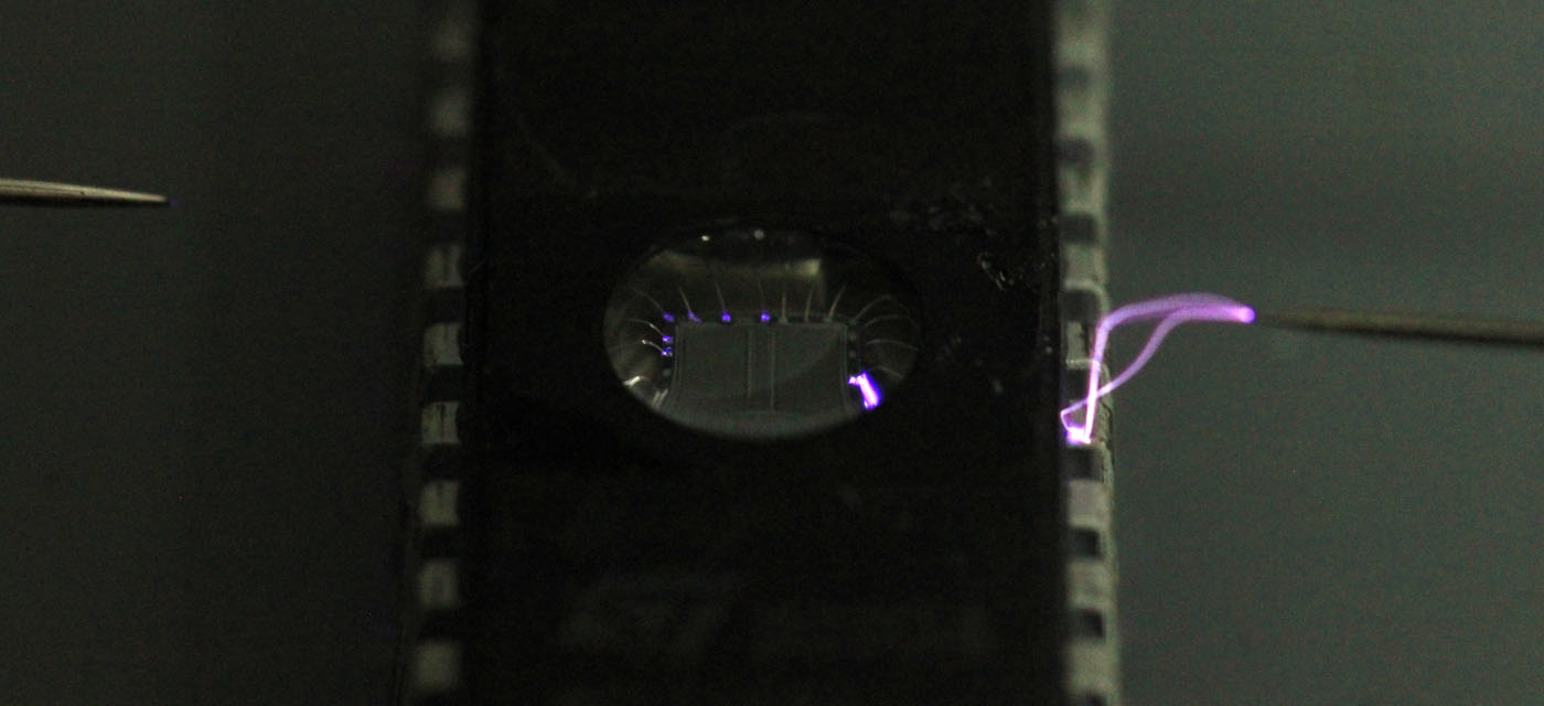
I uploaded two more pictures:
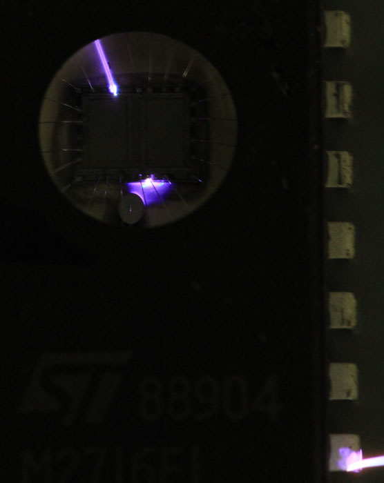
With 20kV the ESD-pad is enough to conduct the high voltage...
Here the positive high voltage has to be on the right side.


