I have this long-term project I started a while ago, which involves building my own LED lamps at little to no cost! I'm still on my 1st lamp, but ultimately I plan to build more, of all forms and shapes, and a wide range of wattages!
I detailed this project
on my website, but I have new pictures of the lamp I'm building at the moment.
What made me want to do this project is a video of a particular LED lamp on YouTube, which used an X2 class capacitor to limit the current instead of a power resistor. I loved the idea, and it's only a matter of recalculating components' values for more or less LEDs, along with adding a few extra components for improved reliability and safety, 'cause I'm paranoid like that, don't judge me! xD
Anyway, before building the actual lamp I first went with a quick prototype on breadboard to make sure all my calculations were correct. Good thing I did, because I got some of them wrong xD. Turned out the value for the capacitor ballast was twice greater than needed, that is, 2uF. A 1uF cap drives the LEDs just fine at 16mA!
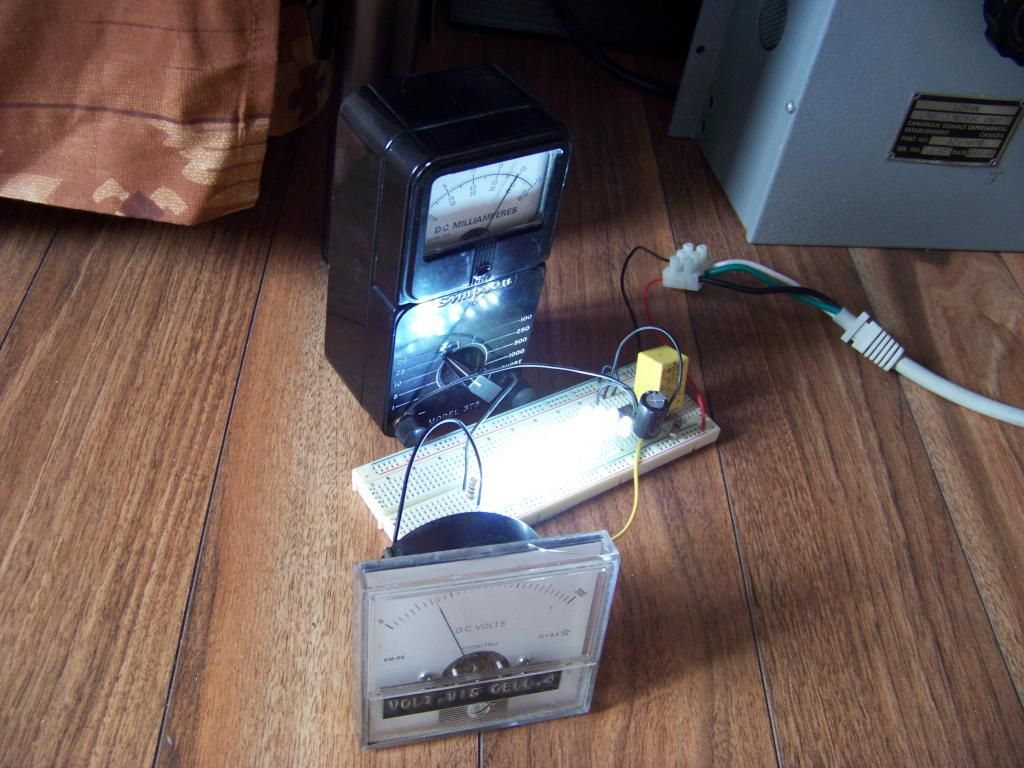
On this pic everything is salvaged from recycling, and I mean EVERYTHING. The wires, the parts, the breadboard, the meters, even the big variac at upper right! I didn't really need to measure the voltage at the bridge rectifier's output, but I had a 0-300V DC voltmeter on hand, and I was curious to know LOL. On the other hand the interesting phenomenon I discovered with this voltmeter is how the circuits reacts when the supply voltage is brought gradually to 120V. The voltage rises steadily, then past a certain point the current starts rising much quicker than voltage before reaching its final value.
After this I was ready to build the lamp itself. I first assembled the LED arrays. I wanted them to illuminate uniformly, unlike many LED lamps I've seen, especially early ones using 5mm LEDs, these were horrible in terms of light distribution!
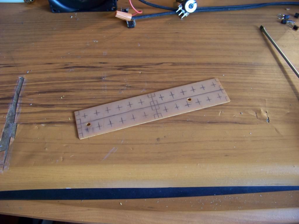
I chose FR2 board material for the structure since I had a piece laying around. It has no copper on it, just a bare phenolic board.
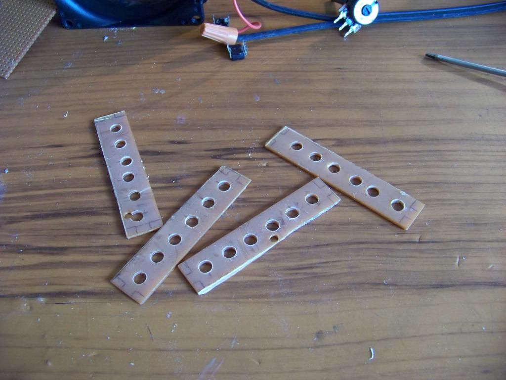
The sides, now ready for the installation of the LEDs. Not the best cutting/drilling job I did to be honest xD
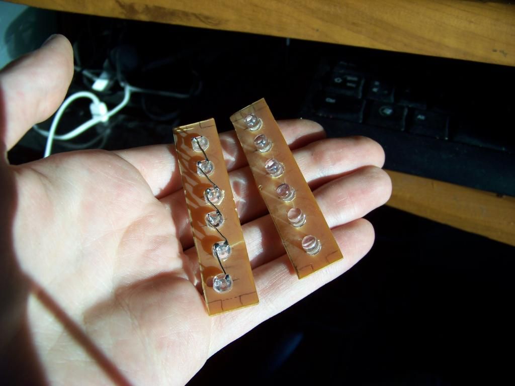
LEDs installed. As you can guess I salvaged them from something else, a wine bottle cooler to be exact. I used jumpers from an old circuit board to connect them together. There's also a smaller square-shaped 4 LED array that'll go on top of the lamp.
Then, the ballast. Because it'll go in the base of an old CFL, I need a round board, or at least something roughly shaped like it.
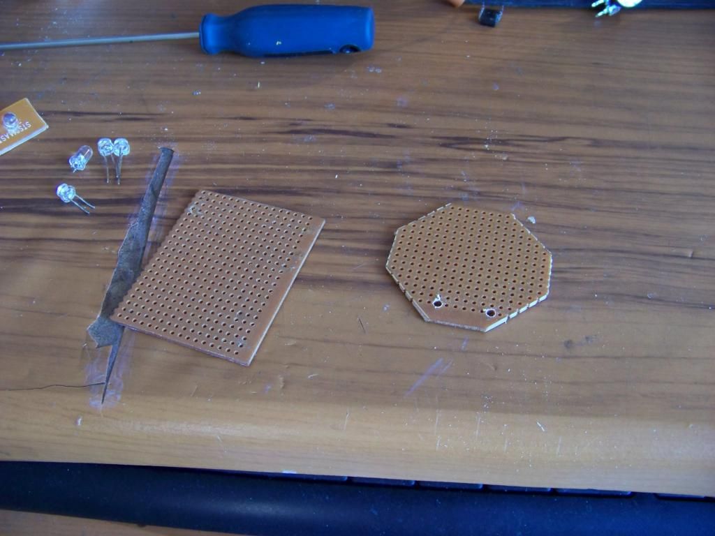
A real prototyping board would probably be better suited than this copper-less board, but again that's what I have available LOL. I made sure the parts had long enough leads so they provide proper support.
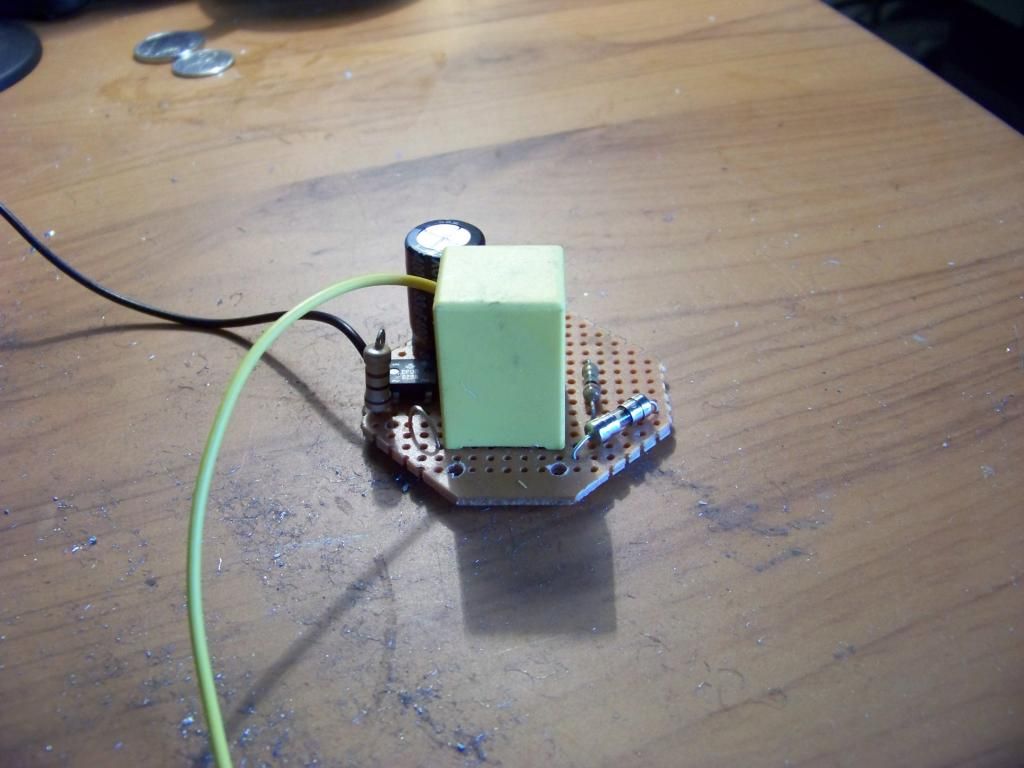
The ballast assembled. The two holes at the front will support the wires from the base. Otherwise the layout is kinda improvised, and likely not the best. The next one will be better! xD
Now I need to figure out how to assemble the parts, especially the LED array. Since it's something that'll be used permanently, I don't want it to fall apart LOL.


