Author Topic: Homebrew digital computer system  (Read 51327 times)

0 Members and 2 Guests are viewing this topic.

Offline GKTopic starter

  • Super Contributor
  • ***
  • Posts: 2607
  • Country: au
Homebrew digital computer system
« on: June 07, 2014, 09:50:01 am »
In my "Homebrew analog computer" thread I mentioned a couple of times that I am planning to build a work-alike to the PDP-8 digital computer. My analog computer construction is temporarily on the back burner again as I wait for a batch of PCB's and semiconductors to arrive. In the meanwhile I have been working on an off on the design of the digital machine. I've done a reasonable amount of prototyping on the bench to verify the constructional blocks of the machine and have the complete specification sorted out. Most of the logic flow diagrams are also worked out.

It's going to be a 12-bit machine with 4096 words of 12-bit memory but a reduced version of the PDP-8's instruction set. One of the "building blocks" I am currently working on the the universal bidirectional 12-bit shift register, for the machines accumulator and program counter. With the exception of the computers memory, the circuitry is going to be entirely discrete transistor.

The heart of the register is 12 clocked data-input, edge triggered flop-flops with control and signal steering logic. The data-flop flops themselves are reasonably complex; each flop-flop consisting of coupled slave and master R-S flop-flop with steering logic to give an edge triggering capability to the clock input that is wholly insensitive to propagation delays. The slaved R-S flop-flop forms a memory element for the data present at the instant of the clock edge.

Here is screen shot of the complete simulation I have up and running of the shift register:


And here it is in operation:


At t=1.3mS the serial data input (second trace from the top) goes high for three clock periods. Consequently 3 active-high bits are shifted through the 12 bits of the register at each successive clock interval. At t=2.7mS, one clock cycle before the last bit is shifted out of the register, the shift-left control input is asserted (third trace from the top) and the data bit is shifted through the register in the opposite direction. This shift register is in fact a universal design which is parallel-programmable, with 12 parallel preset inputs (P0 through P11) in addition to the 12 parallel data outputs (D0 through D11). In the simulated case here the P0-P11 inputs are wired to the D0-D11 inputs to give the reverse ("left") shifting capability (Q1 to P0, Q2 to P1, Q3 to P2, Q4 to P3, etc...)

So here you have the mechanism for the micro-instructions RAL and RAR - rotate accumulator left and rotate accumulator right.

One thing to note is that the entire register (as well as nearly all of the rest of the computers logic) is constructed with a 2 basic building blocks - NAND gates and inverters!:
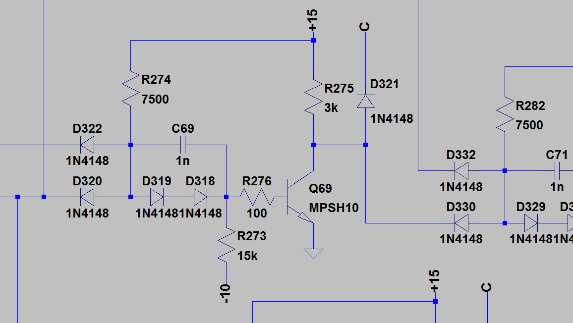


The universal inverter stage is identical to the universal NAND gate, minus an input diode.

Of course all of the above constitutes only a very small part of the project. ATM I am finalizing a PDP-1-like front panel layout for the control console, to send off to Front Panel Express. If there is sufficient interest in such a project I may keep this thread updated as i plod along, perhaps starting next with the machines specification and layout and logic diagram of the shift-resister and the clocked data flip-flops, when I have some more spare time......

« Last Edit: June 12, 2014, 12:57:00 pm by GK »
Bzzzzt. No longer care, over this forum shit.........ZZzzzzzzzzzzzzzzz
 

Offline amyk

  • Super Contributor
  • ***
  • Posts: 8420
Re: Homebrew digital computer system
« Reply #1 on: June 07, 2014, 11:09:47 am »
Very interesting. Did you consider using transparent latches instead (clocking on both positive and negative edges), you may be able to cut the number of components in half.

There's also this circuit for an edge-triggered flipflop which has only 6 NAND gates and could also reduce the number of transistors needed.
 

Offline GKTopic starter

  • Super Contributor
  • ***
  • Posts: 2607
  • Country: au
Re: Homebrew digital computer system
« Reply #2 on: June 07, 2014, 11:55:53 am »
Hmmm... My flop-flop consists of 8 NAND gates plus and inverter. I did experiment with some other arrangements, but I like this one the best because it has a large enough propagation delay safety margin (slave latch timing to the Q output propagating back to the Data input) to be bullet proof assembled from discrete transistor circuitry.

I'm not sure how to simply make a shift register with transparent latches; all instances I've seen with transparent latches are affairs with delay lines and restrictive timing requirements. For example:


Though not the same circuitry my design is topologically (I/O and control) identical to the SN7495, though expanded from 4 stages to 12.
« Last Edit: June 07, 2014, 11:59:37 am by GK »
Bzzzzt. No longer care, over this forum shit.........ZZzzzzzzzzzzzzzzz
 

Offline amyk

  • Super Contributor
  • ***
  • Posts: 8420
Re: Homebrew digital computer system
« Reply #3 on: June 07, 2014, 12:23:41 pm »
Each master-slave flipflop looks like a pair of transparent latches, and one is transparent while the other is latched i.e. one is controlled by the clock, the other by the inverted clock. The signal between these two can also be thought of as storing a bit; so effectively your 12-bit shift register clocked on one edge is a 24-bit shift register clocked on both edges. You only need one (more powerful) inverter to generate an inverted clock for every other latch.
 

Offline GKTopic starter

  • Super Contributor
  • ***
  • Posts: 2607
  • Country: au
Re: Homebrew digital computer system
« Reply #4 on: June 07, 2014, 02:38:04 pm »
Each master-slave flipflop looks like a pair of transparent latches, and one is transparent while the other is latched i.e. one is controlled by the clock, the other by the inverted clock. The signal between these two can also be thought of as storing a bit; so effectively your 12-bit shift register clocked on one edge is a 24-bit shift register clocked on both edges. You only need one (more powerful) inverter to generate an inverted clock for every other latch.

Yes, that is how it works, but the data stored on the slave flip-flops is delayed by a clock cycle, so those 12 "extra" bits are not part of the valid output.
A data flip flop with an edge-triggered clock input is always comprised itself of a master transparent latch and one or more transparent slave latches to provide the clock-edge "instant" memory. However the composite edge-triggered flip-flop thus created (which is the building block for the synchronously-clocked shift register) is not itself transparent. The flip-flops of a synchronous shift register must not be transparent, but edge-triggered for proper operation. 

Consider the simplest shift register of them all  :) , a 1-bit divide by 2 counter:


At the instant the clock input goes high, the logic state of the NOTQ output, as presented to the D input, is transferred to the Q output. This simple circuit cannot work with a data flip-flop that is transparent. The state of the D input at the rising edge of the clock must be latched into a slave memory before the logic state change has a chance to propagate through to the NOTQ output. In other words, the edge-triggered flip-flop must retain a memory for the previously clocked logic state.

True though that I could perhaps save on inverter stages as currently each of the 12 composite edge-triggered flip-flops has its own inverter for the complementary clock signal, but this was done for reasons not apparent in the SPICE simulation. I have not yet decided upon the exact degree of modularization and interconnection of of the various logical "building blocks".
« Last Edit: June 07, 2014, 05:13:34 pm by GK »
Bzzzzt. No longer care, over this forum shit.........ZZzzzzzzzzzzzzzzz
 

Offline GKTopic starter

  • Super Contributor
  • ***
  • Posts: 2607
  • Country: au
Re: Homebrew digital computer system
« Reply #5 on: June 08, 2014, 12:43:49 am »
Does anyone know where I can get toggle switches with actuation levers  like this from?

http://en.wikipedia.org/wiki/EDUC-8#mediaviewer/File:EDUC-8_Microcomputer.jpg
Bzzzzt. No longer care, over this forum shit.........ZZzzzzzzzzzzzzzzz
 

Offline miguelvp

  • Super Contributor
  • ***
  • Posts: 5550
  • Country: us
Re: Homebrew digital computer system
« Reply #6 on: June 08, 2014, 01:13:45 am »
« Last Edit: June 08, 2014, 01:22:10 am by miguelvp »
 

Offline baljemmett

  • Supporter
  • ****
  • Posts: 665
  • Country: gb
Re: Homebrew digital computer system
« Reply #7 on: June 08, 2014, 01:19:09 am »
Does anyone know where I can get toggle switches with actuation levers  like this from?

http://en.wikipedia.org/wiki/EDUC-8#mediaviewer/File:EDUC-8_Microcomputer.jpg

I think the key term is 'paddle', at least it seemed to be when I was looking for similar for my daft computer project.  I settled for some considerably-smaller models from NKK (GW12Lxx, from memory), for space reasons, although they have bigger; I think I also saw some from TE in the sort of size you're probably after, as well as unbranded cheapies on eBay…

(Also going to put my name in the 'certainly interested in this' column, if that helps.  Would definitely be good to see how your front panel comes out, as I'm thinking of using Front Panel Express for mine too!)
 

Offline GKTopic starter

  • Super Contributor
  • ***
  • Posts: 2607
  • Country: au
Re: Homebrew digital computer system
« Reply #8 on: June 09, 2014, 02:40:24 am »
Ah, paddle....... though not on E14's parametric search. I gave up after wading through a few hundred generic toggle and rocker switches.

This series from C&K looks perfect:


Thanks...

I'll post up photos of my front panel when it arrives. Of course I need to find the right switches before I can finalize the layout. However reviewing my computers specification and thinking it over the past two evenings I am now procrastinating over whether or not to stick to the current 12-bit "PDP-8" specification or to scrap the current control panel layout and begin again to a 16-bit specification. Of course, with 16-bits it will no longer be a PDP-8 work-alike. The reason I am contemplating shifting to 16 bits is because it means that I can significantly simplify the memory addressing and make a whole machine cycle redundant.

The current specification, as per the PDP-8, uses 3 bits of the 12 bit instruction word (IW)  for the instruction code. For memory-reference instructions, of which there are 6, 7 bits address the operand directly. This means that only 128 words of the 4096 word memory is directly addressable. The two remaining bits of the IW, designated I and Z, are used for memory page control. Z=1 concentates the 5 MSB's of the current IW address location with the 7 address bits of the IW to give a 12-bit address number, giving fiddly and limited access to the full 4096 words. I=1 activates indirect addressing, in which the 7 address bits of the IW do not specify the memory location of the operand, but instead point to a memory location containing a 12-bit word specifying the memory location of the operand.

Indirect addressing requires an additional machine cycle and complicates the control logic significantly. In my specification the three machine cycles are fetch, defer and execute. Defer is only enacted for indirect addressing. If I increase my computers bit length to 15-bit, I'd have enough bits in an IW to address the full 4096 words of memory directly. The defer machine cycle and attendant control logic would be rendered redundant. 15-bit is divisible by 3 and is thus nice and neat in octal representation 32767 dec. = 111 111 111 111 111 bin. = 77777 oct. However I think more in hex so I think 16 bits just feels more right.

However with 16 bits I could increase my memory specification from 4096 words to 8192 and still maintain direct addressing of the full memory. I have to spend the rest of my day off now cutting lawns and hedge trimming. I'll ruminate over the decision of 12 or 16 bits a little longer...........

What MCU is basis for your computer project? 
« Last Edit: June 09, 2014, 02:52:01 am by GK »
Bzzzzt. No longer care, over this forum shit.........ZZzzzzzzzzzzzzzzz
 

Offline woodchips

  • Frequent Contributor
  • **
  • Posts: 600
  • Country: gb
Re: Homebrew digital computer system
« Reply #9 on: June 11, 2014, 09:27:20 am »
Might be of interest but several people on the vintage-computer.com forum are building PDP8 look alikes.

Not a machine I know anything much about, but why is it so popular? The PDP11 seems a vastly more elegant design.
 

Offline amyk

  • Super Contributor
  • ***
  • Posts: 8420
Re: Homebrew digital computer system
« Reply #10 on: June 11, 2014, 10:44:31 am »
Depends what you want to do; if you just want to build a working computer then 12 bits (or 8) would be enough. If you go to 16 bits and make it PDP-11 compatible, maybe you could even run an early Unix on it.
 

Offline GKTopic starter

  • Super Contributor
  • ***
  • Posts: 2607
  • Country: au
Re: Homebrew digital computer system
« Reply #11 on: June 12, 2014, 12:49:38 pm »
Yeah, but the PDP-11 came to the market around 10 years later I think. The PDP-8 was the first really successful "minicomputer", so its own special place in history.
I've decided to do my own thing and go the 16-bit route with my design. Some of my switch components have already turned up and attached is a *.pdf of how far I have gotten so far with the new front panel design. There's enough detail on it already to make most of the computers specification clear (including all of the instructions). I don't have the time to collate my books of notes in a presentable form right now though; so just a minor progress update  ;)

Bzzzzt. No longer care, over this forum shit.........ZZzzzzzzzzzzzzzzz
 

Offline GKTopic starter

  • Super Contributor
  • ***
  • Posts: 2607
  • Country: au
Re: Homebrew digital computer system
« Reply #12 on: June 12, 2014, 12:54:09 pm »
Oh, and here is the discrete diode-transistor-logic, edge-triggered DFF that I built for evaluation. The scope traces are clock in (negative edge trigger) in yellow and the Q output in blue. The NOTQ output is wired to the D input, so the DFF acts as a divide-by-2 counter. Propagation delay from CLK in to Q out is approx 100nS.
The logic runs from power supply voltages of +15V and -10V while the logic high level is a little under 4V - clamped at 5 Si diode drops. This is a design technique that dates back right to the first bipolar transistor computers - it gives much improves power supply noise/spike immunity. In the high state, the output voltage is diode-clamped, so fluctuations on the positive supply rail are not transmitted to the logic output. Also a negative supply rail is utilized to enable the switching transistor Vbe junctions to be reverse biased in the off state (in the case here by ~1 Si diode drop). This greatly improves the logic gates immunity to ground noise/bounce/spikes/etc. These kind of design details are important when you are dealing with switching logic circuity drawing amperes of current and spread out over large areas due to the physical bulk of all those discrete through-hole components.   


« Last Edit: June 12, 2014, 01:48:05 pm by GK »
Bzzzzt. No longer care, over this forum shit.........ZZzzzzzzzzzzzzzzz
 

Offline SeanB

  • Super Contributor
  • ***
  • Posts: 16366
  • Country: za
Re: Homebrew digital computer system
« Reply #13 on: June 12, 2014, 05:52:45 pm »
While you are at the design stage why not reinvent the original IC and make a small package scale device that has one or two logic elements on it, sort of like a discrete IC. That way it will be easier to simply have a baseboard with the interconnects and simply solder the mini boards to it, like the original computers did. SMT with a SIL type format will be pretty high packing density, and still easy enough to troubleshoot.
 

Offline SirNick

  • Frequent Contributor
  • **
  • Posts: 589
Re: Homebrew digital computer system
« Reply #14 on: June 12, 2014, 06:48:32 pm »
I've always admired these kinds of projects.  Totally impractical, but just so cool.   8)  In a really nerdy kind of way, of course.  If I didn't have a hundred (practical) projects on my to-do list, I would love to build a computer from scratch.

BTW, have you ever ordered from FPE?  I have a few subwoofer plate amps I've had made from them.  They do good work.  Gets pricey really quick though, and I really wish they would do silk screening.
 

Offline GKTopic starter

  • Super Contributor
  • ***
  • Posts: 2607
  • Country: au
Re: Homebrew digital computer system
« Reply #15 on: June 17, 2014, 12:34:26 pm »
Yes, I have ordered from FPE before. The only thing in which they have been remiss is packaging. I had to spend half an hour with a rubber mallet and a blanket to straighten my last panel. It was posted just sandwiched between sheets of cardboard.
Bzzzzt. No longer care, over this forum shit.........ZZzzzzzzzzzzzzzzz
 

Offline GKTopic starter

  • Super Contributor
  • ***
  • Posts: 2607
  • Country: au
Re: Homebrew digital computer system
« Reply #16 on: July 07, 2014, 09:19:36 am »


There's also this circuit for an edge-triggered flipflop which has only 6 NAND gates and could also reduce the number of transistors needed.


After some further analysis and prototyping, that has become my DFF of choice for this project. Unlike the 8-AND plus 2-INV "Master/Slave" DFF, that one is pure edge-triggered, rather than just edge-triggered, to use the established nomenclature, which is preferable due to the absence of "ones catching" and thus greater noise immunity. It's quite an ingenious circuit. I've done a comprehensive timing analysis and it's virtually immune to race conditions and totally robust even built sloppily with discrete DTL NAND gates.
There is a slight variation of the circuit to transform it into a JK FF, which is is now the basis of my synchronous counters. Asynchronous Set and Clear inputs are also easily added to both D and JK variants without having to add additional gates (just an extra input to several). More details in the not too distant future.....
   
Bzzzzt. No longer care, over this forum shit.........ZZzzzzzzzzzzzzzzz
 

Offline GKTopic starter

  • Super Contributor
  • ***
  • Posts: 2607
  • Country: au
Re: Homebrew digital computer system
« Reply #17 on: July 07, 2014, 09:28:15 am »
I've spent a lot of time procrastinating over the physical construction of this machine, and here is what I have finally come up with. It's a PCB card frame scheme that I can fabricate with my limited home workshop facilities and works out a great deal cheaper than any commercially available system; eg Eurocard.

My plug-in circuit cards are 300mm X 150mm with DIN41612 connectors. The rear panel of the card frame will form a hardwired backplane. I've managed to construct one of the intermediate card frame shelves so far. This card frame is to be mounted into a 19" relay rack. No use for further words as pictures reveal enough.......


« Last Edit: July 07, 2014, 09:36:15 am by GK »
Bzzzzt. No longer care, over this forum shit.........ZZzzzzzzzzzzzzzzz
 

Offline GKTopic starter

  • Super Contributor
  • ***
  • Posts: 2607
  • Country: au
Re: Homebrew digital computer system
« Reply #18 on: July 07, 2014, 09:43:36 am »
Oh, and I've just finished the computers front/control panel design. Here it is. Time for dinner now though. It just needs double checking after a break and then I will send it off to FPE for manufacture.

https://www.eevblog.com/forum/projects/homebrew-digital-computer-system/?action=dlattach;attach=101246

EDIT: attachment updated
« Last Edit: July 09, 2014, 09:54:32 am by GK »
Bzzzzt. No longer care, over this forum shit.........ZZzzzzzzzzzzzzzzz
 

Offline bwat

  • Frequent Contributor
  • **
  • Posts: 278
  • Country: se
    • My website
Re: Homebrew digital computer system
« Reply #19 on: July 07, 2014, 09:44:00 am »

This bibliophile needs to know what book this is.
"Who said that you should improve programming skills only at the workplace? Is the workplace even suitable for cultural improvement of any kind?" - Christophe Thibaut

"People who are really serious about software should make their own hardware." - Alan Kay
 

Offline GKTopic starter

  • Super Contributor
  • ***
  • Posts: 2607
  • Country: au
Re: Homebrew digital computer system
« Reply #20 on: July 07, 2014, 09:49:09 am »
This bibliophile needs to know what book this is.


Pulse, Digital and Switching Waveforms, Millman and Taub.

Also see the chapter on registers and counters in this (now public domain) book (for said building blocks realized with time delays rather than, as yet uninvented, edge-triggered flip flops).

https://ia600304.us.archive.org/20/items/DesignOfTransistorizedCircuitsForDigitalComputers/pressman.djvu
« Last Edit: July 07, 2014, 09:51:54 am by GK »
Bzzzzt. No longer care, over this forum shit.........ZZzzzzzzzzzzzzzzz
 

Offline bwat

  • Frequent Contributor
  • **
  • Posts: 278
  • Country: se
    • My website
Re: Homebrew digital computer system
« Reply #21 on: July 07, 2014, 09:55:20 am »
Thanks!
"Who said that you should improve programming skills only at the workplace? Is the workplace even suitable for cultural improvement of any kind?" - Christophe Thibaut

"People who are really serious about software should make their own hardware." - Alan Kay
 

Offline GKTopic starter

  • Super Contributor
  • ***
  • Posts: 2607
  • Country: au
Re: Homebrew digital computer system
« Reply #22 on: July 07, 2014, 12:51:32 pm »
Here is a question for any old timers out there with PDP experience ;D

Although my computers specification and logic design is already done and I am not going to change it, does anyone know why the micro instructions of the OPR (operate) instruction were not simply binary encoded? I mean, it just seems odd to toggle a specific bit to enable a specific micro instruction. And then of course there isn't enough individual bits for all of the micro instructions, so they are divided up into groups that are selected by toggling 2 other bits.

My computer has 13 micro instructions (well 14 including NOP, which is enabled by setting all free bits 0), but I don't have to worry about grouping as my instruction word is 16-bits, and that gives 13 free bits minus the 3 for the operation code. My priority system for combined micro instructions operates independently of the instruction decoder. However if I was designing a computer with an extended instruction set, such that I did not have enough individual bits to toggle all of my micro instructions, it would seem much more logical to simply binary encode the micro instruction selection rather than dividing them into groups and sticking with bit-toggling.


« Last Edit: July 07, 2014, 12:55:13 pm by GK »
Bzzzzt. No longer care, over this forum shit.........ZZzzzzzzzzzzzzzzz
 

Offline dfmischler

  • Frequent Contributor
  • **
  • Posts: 548
  • Country: us
Re: Homebrew digital computer system
« Reply #23 on: July 07, 2014, 01:45:31 pm »
... it just seems odd to toggle a specific bit to enable a specific micro instruction. And then of course there isn't enough individual bits for all of the micro instructions, so they are divided up into groups that are selected by toggling 2 other bits.
... if I was designing a computer with an extended instruction set, such that I did not have enough individual bits to toggle all of my micro instructions, it would seem much more logical to simply binary encode the micro instruction selection rather than dividing them into groups and sticking with bit-toggling.

I assume you mean PDP-8 (e.g. PDP-15 has 18 bit instructions and more opcode bits).  The PDP-8 group 1 operate instructions are bit-encoded both for simplicity of implementation (e.g. big decoders or ROMs would have had to be made out of lots of diodes), and because they can be combined in a single operation to give specific operations or values (e.g. on a PDP-8/I you could combine CLA CLL RTL IAC [7307] to generate the value 4 in the accumulator; I'm told this didn't work on the original /8 because rotating and incrementing the accumulator couldn't be combined).  CLA CLL CMA RAR [7350] would set the accumulator to 3777 (the most positive number).  CMA IAC [7041] (complement and increment the accumulator) was idiomatic for taking the 2's complement (arithmetic negative) of a value.  And so on.

In the group 2 operate instructions you can likewise combine the skip bits to put together composite conditions: SMA SZA SNL would skip if any of the conditions SMA (Minus Accumulator: high bit of accumulator is set), SZA (Zero Accumulator), or SNL (Nonzero Link) was true.  If you just added two positive values then SMA SNL skips if there is an overflow condition.  The AND group bit merely complements the result of the OR group conditions.  It's clever and takes few diodes and transistors to implement as compared to making a big decoder.  Work it out in terms of gates and you will see how simple a design it is.
« Last Edit: July 07, 2014, 09:42:50 pm by dfmischler »
 

Offline GKTopic starter

  • Super Contributor
  • ***
  • Posts: 2607
  • Country: au
Re: Homebrew digital computer system
« Reply #24 on: July 07, 2014, 03:07:11 pm »
You can still combine micro instructions with binary encoding, and with even greater flexibility. With binary encoding the micro instructions can be weighted to define their priorities, which does mitigate the extra complexity of the required instruction decoding to some degree, and you're then not confined to being able to only combine micro instructions within a single group, which, upon superficial examination, seems to me the greatest limitation of the PDP8 specification.
At least that is how I drafted it out in block diagram before opting for a slightly reduced instruction set selected in the traditional (albeit ungrouped) way with my 13 bits. I would love to do an extended instruction set with binary encoding and unrestricted, albiet prioritized combination, but I have to rationalize the specification and complexity to some point. I am just a single person with a single soldering iron building something in his free time.


« Last Edit: July 07, 2014, 03:20:20 pm by GK »
Bzzzzt. No longer care, over this forum shit.........ZZzzzzzzzzzzzzzzz


Share me

Digg  Facebook  SlashDot  Delicious  Technorati  Twitter  Google  Yahoo
Smf