Author Topic: General Purpose Power Supply Design  (Read 215476 times)

0 Members and 10 Guests are viewing this topic.

Offline amspireTopic starter

  • Super Contributor
  • ***
  • Posts: 3802
  • Country: au
Re: General Purpose Power Supply Design
« Reply #150 on: April 22, 2012, 12:47:19 pm »
Is there anything for 10 times the cost  that comes close?
Dave has an episode on precision voltage reference that is nothing more than a voltage reference IC and a bunch of resistor dividers in a box.
Just a bunch of resistors.  ::)

I would love place I could just buy that bunch of resistors at an affordable price. It is very easy to underestimate what Krohn-Hite had to do to get that bunch of resistors. You don't get anything with custom matched resistors like that for anywhere near $1000 new. Out of the range of hobbyists for sure.

Quote

I know you are excited!  :)

But by the time you put $1 something-duino in a rack enclosure, add power supply, user interface, go through agencies approvals,  issue calibration certificate, print user manual and product shipping package (so that it can be sold side-by-side with big guys) it will cost $500.

Leo
Which is why I am not getting involved with that. My PWM DAC is for a basic power supply. The fact it will have a D/A that will probably kill anything in commercial power supplies for 100 times the price is OK - I am not complaining.

If I design a precision programmable voltage reference as well, I think it would be ideal as a hobbyist project - they can make something for $10 - $20 that is probably better then that $500+ commercial stuff that you are talking about.

Richard.
« Last Edit: April 22, 2012, 12:56:44 pm by amspire »
 

Offline BravoV

  • Super Contributor
  • ***
  • Posts: 7549
  • Country: 00
  • +++ ATH1
Re: General Purpose Power Supply Design
« Reply #151 on: April 24, 2012, 04:26:29 am »
If you look at the 14V reading, you see that as I approach the higher voltages, the error seems to be increasing. The error of .2mV amounts to a 15ppm error. A 50ppm/C metal film resistor in my LM324 amplifier circuit feedback can cause this if the resistor's temperature warms by just 0.33 deg C as the voltage across it increases. Also I have scaled this for 25V full scale, so an error of 0.2mV is just 8ppm of full scale. I really think this is amazing from such a simple circuit.

I am really on the limits of basic resistor and LM324 performance here. For my power supply, I am very happy to go for 10mV absolute accuracy, with typical accuracy being 1mV, and it looks like I get that with the most basic of parts.

I cannot see any reason why the results would not be even better with high stability resistors and ultra low offset & current opamps.

Richard, I'm guessing that the resistors you're talking about are those in the 3 stages RC filter ?

Btw, cmiiw, looks like now you've finalized the adjustable vref module right ? How is the linear power part, are you going to work on that soon ?

Offline BravoV

  • Super Contributor
  • ***
  • Posts: 7549
  • Country: 00
  • +++ ATH1
Re: General Purpose Power Supply Design
« Reply #152 on: April 24, 2012, 04:41:56 am »
Is there anything for 10 times the cost  that comes close?
Dave has an episode on precision voltage reference that is nothing more than a voltage reference IC and a bunch of resistor dividers in a box.
I don't think those resistors are just jelly bean resistors, suggesting you to search here at this forum on the metrology discussions, there are plenty of it here, and Richard was also quite active in those discussions, I believe he knows what he is talking about when it comes to resistor in precision circuit.

Offline amspireTopic starter

  • Super Contributor
  • ***
  • Posts: 3802
  • Country: au
Re: General Purpose Power Supply Design
« Reply #153 on: April 24, 2012, 06:27:06 am »
If you look at the 14V reading, you see that as I approach the higher voltages, the error seems to be increasing. The error of .2mV amounts to a 15ppm error. A 50ppm/C metal film resistor in my LM324 amplifier circuit feedback can cause this if the resistor's temperature warms by just 0.33 deg C as the voltage across it increases. Also I have scaled this for 25V full scale, so an error of 0.2mV is just 8ppm of full scale. I really think this is amazing from such a simple circuit.

I am really on the limits of basic resistor and LM324 performance here. For my power supply, I am very happy to go for 10mV absolute accuracy, with typical accuracy being 1mV, and it looks like I get that with the most basic of parts.

I cannot see any reason why the results would not be even better with high stability resistors and ultra low offset & current opamps.

Richard, I'm guessing that the resistors you're talking about are those in the 3 stages RC filter ?

Btw, cmiiw, looks like now you've finalized the adjustable vref module right ? How is the linear power part, are you going to work on that soon ?

I am entering the circuit into KiCad, but I admit, once I post it, I could really do with some ideas about the interface.

The cheapest approach would be to use an ATtiny processor with the QTouch hardware for capacitive buttons, but a power supply without a knob or two and real switches? - I just do not know.

Every half decent power supply I have built or used can easily last for decades. I want to end up with something that has an efficient interface that lets me switch from rough control to very fine easily.

Richard.
 

Offline amspireTopic starter

  • Super Contributor
  • ***
  • Posts: 3802
  • Country: au
Re: General Purpose Power Supply Design
« Reply #154 on: April 24, 2012, 06:40:04 am »
Richard, I'm guessing that the resistors you're talking about are those in the 3 stages RC filter ?
No The resistors and the capacitors in the RC filter can be very cheap - it doesn't matter. As long as the capacitors do not have a really bad ESR and as long as the leakage current is negligible. Drift in the filter resistors cause no real error, so the only problems are if they have a big effective parallel capacitance or are really noisy.

I need to amplify the output of the DAC up to the actual intended supply voltage, so that might mean amplifying by a factor of up to 8 times. The resistors in that amplifier will probably cause more error then the PWM dac. It really does not matter though. If a basic 25V supply is accurate to 10mV, that is impressive. I am not going to try for 100uV accuracy for the power supply. If I need high stability, I am happy to run the supply for half an hour to let it stabilize thermally.

Richard.
 

Offline markus_b

  • Regular Contributor
  • *
  • Posts: 115
  • Country: ch
Re: General Purpose Power Supply Design
« Reply #155 on: April 24, 2012, 06:48:54 am »
Every half decent power supply I have built or used can easily last for decades. I want to end up with something that has an efficient interface that lets me switch from rough control to very fine easily.
I would go for a rotary encoder. Turning a knob is still the best use-interface for fine-tuning stuff. If you take one with a built-in push-button you can switch between fast/slow easily. I also like software-controlled accelleration. If you turn is slowly you change in 1mV steps if you turn faster it changes in 10mV steps, if you turn very fast you change in 100mV steps.

Also a rotary encoder needs 2 pins, like two pushbuttons, there is no difference in consumption of port pins.
Markus

A good scientist is a person with original ideas. A good engineer is a person who makes a design that works with as few original ideas as possible.
 

Offline amspireTopic starter

  • Super Contributor
  • ***
  • Posts: 3802
  • Country: au
Re: General Purpose Power Supply Design
« Reply #156 on: April 24, 2012, 07:18:15 am »
Every half decent power supply I have built or used can easily last for decades. I want to end up with something that has an efficient interface that lets me switch from rough control to very fine easily.
I would go for a rotary encoder. Turning a knob is still the best use-interface for fine-tuning stuff. If you take one with a built-in push-button you can switch between fast/slow easily. I also like software-controlled accelleration. If you turn is slowly you change in 1mV steps if you turn faster it changes in 10mV steps, if you turn very fast you change in 100mV steps.

Also a rotary encoder needs 2 pins, like two pushbuttons, there is no difference in consumption of port pins.
That is the direction I am leaning, even though it means a more complex build.

One of the build options I have been considering is a small box (battery or power adapter powered) like a large smartphone size and about 15mm - 20mm thick. With touch switches, the back of the PCB can also form the top of the case, with perhaps a thin plastic sheet on top. This would be a lower power version - perhaps 200mA. I do not need a heatsink, so the actual power supply board using surface mount parts can be very thin.

You would have this sitting flat on the bench right next to the load. Once I start adding knobs and switches though, I am not sure that idea works as well. If I add a knob, it will probably have to be one that can be switched between volts and current adjust easily.

Dave is right about the importance of packaging. It is probably the hardest part of the project.

Richard.
 

Offline BravoV

  • Super Contributor
  • ***
  • Posts: 7549
  • Country: 00
  • +++ ATH1
Re: General Purpose Power Supply Design
« Reply #157 on: April 24, 2012, 07:37:45 am »
Richard, forgot to ask, on the pwm generator, what is your decision ? A separated and dedicated mcu for pulse generation ?

Offline markus_b

  • Regular Contributor
  • *
  • Posts: 115
  • Country: ch
Re: General Purpose Power Supply Design
« Reply #158 on: April 24, 2012, 07:55:51 am »
Dave is right about the importance of packaging. It is probably the hardest part of the project.
Yes, very true.

I'm leaning towards a similar small box as Dave is using. I like the vertical front as this allows me to stack them up on the shelf. I may have several of them.

For Volts/Amps I think I prefer separate knobs. You could also switch between the two using the pushbutton, but there is always the danger that you change the wrong thing. Some additional buttons for special functions would be nice too. Something like 'Menu', 'OK', 'Cancel'.

I also like a graphic LCD, something like the 65x128 display from newhaven. Does not cost more than a character display, but gives more options for future firmware with interesting features, like displaying current spikes, etc. The only catch is that you think I'd need a microcontroller with enough flash to hold a character table.
Markus

A good scientist is a person with original ideas. A good engineer is a person who makes a design that works with as few original ideas as possible.
 

Offline amspireTopic starter

  • Super Contributor
  • ***
  • Posts: 3802
  • Country: au
Re: General Purpose Power Supply Design
« Reply #159 on: April 24, 2012, 08:07:37 am »
Richard, forgot to ask, on the pwm generator, what is your decision ? A separated and dedicated mcu for pulse generation ?
A single micro in the supply.

The PWM drives a cmos logic gate powered by the reference to generate the precision PWM output. I will probably stick to an Arduino processor, but I will have to see how the pin allocation goes - there are never enough. I see programming a micro as being a frustration to many people who want to build the supply, and Arduino probably gives the easiest way in. You can buy a $20 Arduino, and use it to program another blank Atmega IC - or you can just buy the IC pre-programmed with bootloader from any Arduino supplier.

There are great chips in TI's MSP430 family, but there is just no cheap way to program them. As far as I know, the cheapest way to start is a $99 device from TI.

Richard.
 

Offline markus_b

  • Regular Contributor
  • *
  • Posts: 115
  • Country: ch
Re: General Purpose Power Supply Design
« Reply #160 on: April 24, 2012, 08:27:37 am »
The PWM drives a cmos logic gate powered by the reference to generate the precision PWM output. I will probably stick to an Arduino processor, but I will have to see how the pin allocation goes - there are never enough. I see programming a micro as being a frustration to many people who want to build the supply, and Arduino probably gives the easiest way in. You can buy a $20 Arduino, and use it to program another blank Atmega IC - or you can just buy the IC pre-programmed with bootloader from any Arduino supplier.
Why not building it as Arduino shield ?

Then you can concentrate on the power stuff and sort of offload the microcontroller/programming related worries to the Arduino. Things like providing a chip with an Arduino bootloader will be take care of. It also sort of fixes the form-factor.
Markus

A good scientist is a person with original ideas. A good engineer is a person who makes a design that works with as few original ideas as possible.
 

Offline Leo Bodnar

  • Frequent Contributor
  • **
  • Posts: 814
  • Country: gb
Re: General Purpose Power Supply Design
« Reply #161 on: April 24, 2012, 09:38:53 am »
Have you considered using standard 24 or 18 bit delta-sigma audio DAC?  They are very cheap and interfacing to I2S is trivial.  You can drop the sampling clock rate to match your MCU internal frequency.

Leo

Offline amspireTopic starter

  • Super Contributor
  • ***
  • Posts: 3802
  • Country: au
Re: General Purpose Power Supply Design
« Reply #162 on: April 24, 2012, 11:08:46 am »
Have you considered using standard 24 or 18 bit delta-sigma audio DAC?  They are very cheap and interfacing to I2S is trivial.  You can drop the sampling clock rate to match your MCU internal frequency.

Leo
The problem is they are not designed for DC stability, and there is usually nothing in the spec to tell you much about DC stability. They may be cheap, but cheaper then a few resistors and capacitors, and a cmos gate IC? Also, the idea of this design was as much as possible use common parts - the delta-sigma DACs are moving slightly to the exotic.

Basically, as far as I can see, the micro implements a delta-sigma dac almost perfectly, so in a sense, I already have one. Why buy another?

Richard.
 

Offline Leo Bodnar

  • Frequent Contributor
  • **
  • Posts: 814
  • Country: gb
Re: General Purpose Power Supply Design
« Reply #163 on: April 24, 2012, 11:26:15 am »
Basically, as far as I can see, the micro implements a delta-sigma dac almost perfectly, so in a sense, I already have one. Why buy another?
To reduce output settling time by the factor of 1000?

Leo

Offline amspireTopic starter

  • Super Contributor
  • ***
  • Posts: 3802
  • Country: au
Re: General Purpose Power Supply Design
« Reply #164 on: April 24, 2012, 12:37:19 pm »
Basically, as far as I can see, the micro implements a delta-sigma dac almost perfectly, so in a sense, I already have one. Why buy another?
To reduce output settling time by the factor of 1000?

Leo
It could be worth it for some people if you can tell me some DC stability specs for the delta-sigma converters.

I am pretty happy with the settling time I have for manual use, but it would be useless for, say, remotely controlled automated testing. Fast settling specs can become useless if the supplies do not have active pull down on the output - something I am considering.

Richard.
 

Offline free_electron

  • Super Contributor
  • ***
  • Posts: 8550
  • Country: us
    • SiliconValleyGarage
Re: General Purpose Power Supply Design
« Reply #165 on: April 24, 2012, 02:07:51 pm »
I have to admit that i have not read the whole topic, but just a quick sidenote ( this may or may not have been covered )
Are you using a PWM or a BRM ? In a BRM the pulse width is always fixed but the delay between them changes. This is typically made with an accumulator and checking for overflow.

In cpus this is very efficient.

Slow Timed interrupt :
Add reg, rate
If carry then {flag = true, clear carry}
Output = flag.
Return

Fast timed interrupt:
Flag =false
Return

Fast timed interrupt needs highest priority. So it can clear the flag.
Professional Electron Wrangler.
Any comments, or points of view expressed, are my own and not endorsed , induced or compensated by my employer(s).
 

Offline amspireTopic starter

  • Super Contributor
  • ***
  • Posts: 3802
  • Country: au
Re: General Purpose Power Supply Design
« Reply #166 on: April 24, 2012, 02:17:11 pm »
I have to admit that i have not read the whole topic, but just a quick sidenote ( this may or may not have been covered )
Are you using a PWM or a BRM ?
I am using PWM. It turned out to be very important that I was modulating an 8 bit PWM, as it means the fundamental PWM frequency is always 62.5KHz and this is high enough to be very effectively filtered out to DC. 16 bit PWM or BRM can end up with much lower frequency fundamentals that do not get fully removed by the filter.

Richard.
 

Offline ejeffrey

  • Super Contributor
  • ***
  • Posts: 3932
  • Country: us
Re: General Purpose Power Supply Design
« Reply #167 on: April 24, 2012, 03:31:24 pm »
I am using PWM. It turned out to be very important that I was modulating an 8 bit PWM, as it means the fundamental PWM frequency is always 62.5KHz and this is high enough to be very effectively filtered out to DC. 16 bit PWM or BRM can end up with much lower frequency fundamentals that do not get fully removed by the filter.

You should be aware that PWM can also generate low frequency components depending on the output code.  For instance, if you have 8 bit PWM @ 62.5 KHz and output the 24 bit code 0x800100 your PWM will be 0x80 for 255 cycles and 0x81 for 1 cycle, giving you a pulses at 244 Hz.  To solve this you have to use a multi-order sigma-delta. Basically this will allow the feedback loop to overshoot and use codes 0x7F and 0x81.  This pushes the noise to higher frequency where they can be filtered more effectively.
 

Offline amspireTopic starter

  • Super Contributor
  • ***
  • Posts: 3802
  • Country: au
Re: General Purpose Power Supply Design
« Reply #168 on: April 25, 2012, 01:12:04 am »

You should be aware that PWM can also generate low frequency components depending on the output code.  For instance, if you have 8 bit PWM @ 62.5 KHz and output the 24 bit code 0x800100 your PWM will be 0x80 for 255 cycles and 0x81 for 1 cycle, giving you a pulses at 244 Hz.  To solve this you have to use a multi-order sigma-delta. Basically this will allow the feedback loop to overshoot and use codes 0x7F and 0x81.  This pushes the noise to higher frequency where they can be filtered more effectively.
I haven't looked at a multi-order sigma delta at all yet, but it sounds like more cycles of processing in the PWM interrupt that can be a problem. Until I was told, I never knew I was designing a delta-sigma PWM.

But to really understand the noise from my PWM, we have to do some really difficult and complex calculations - well actually no, it turns out to be extremely easy. Don't need to look at a single textbook. Just a bit of LTSpice.

Lets just take my RC filter time constant (100K/0.22uF) as fixed, the micro speed (16MHz) as fixed and the PWM speed (62.5KHz) as fixed. The rejection of anything above above 1Khz is close to absolute - less then 30nV rms on the 25V power supply output. To verify that, all you have to do is work out the impedance of the .22uF cap at 1KHz, and then use that to work out the attenuation of each stage.  As a result, we can ignore totally the normal 62KHz PWM output, and all we have to look at is the effect of the corrections - we can treat them as separate pulses.

The worse case is a single correction pulse, all thanks to the way the algorithm I am using that spreads corrections out evenly.

A single pulse when scaled to the output voltage is 30V in amplitude and 62.5 nS wide (1/16MHz). Here is the result at the output for a 3 stage RC filter and a 6 stage RC filter. The input pulse is too short to plot in the graph but it is there at time 0.0:
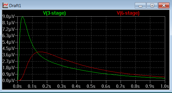


These waveforms say everything. The worse case noise will be 9uV p-p which means the worse case RMS noise will be around 3uV RMS. If I used a 6 stage filter, you get about half this.

I think the truth is that 9uV of low frequency noise is low enough to be fine - Agilent are proud to boast that their E36xx series supplies have less then 0.35mV of RMS noise.  However, all  you need to do to reduce the noise further is to control the minimum rate of the error correction. It is a very simple matter of controlling the resolution of the PWM numbers I use. Lets use pulses at 20Hz. you get this:
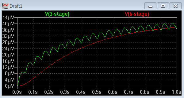


The 3 stage filter noise has dropped to just over 1uV RMS, and with a 6 stage filter, the noise is essentially gone.
The cost of limiting the minimum correction pulse frequency to 20Hz is that you loose resolution - the smallest adjustment step is 40uV. What is happening is the next correction pulse arrives well before the first has decayed so they combine reducing the peak to peak noise.

I prefer to leave the resolution unlimited, and the user can add a big cap on the supply output terminals if they need lower ripple for some reason. I just think that if you are trying to run a circuit from a power supply that is sensitive to very low frequency noise at the uV level, you will be struggling anyway, particularly if the supply has noise generating microprocessors, a switching pre-regulators, etc.

For people who want minimum noise at the expense of resolution, it is one line of code that needs to be changed.

I could go to a 6 stage filter, but I am not sure it is worth the trouble. I just do not think anyone will notice the difference in reality. With one more capacitor in the gain stage that amplifies the reference output, I can reduce the worse case peak-to-peak noise from 9uV to 5uv and that is probably where I will stop.

It's good enough. It is easy to get carried away with making the numbers look perfect when in reality, it just does not matter. When your load current increases by 1mA, you will get a 9uV+ change anyway due to the resistance of your power leads to the load.

Richard.

EDIT: Thinking about this a bit more, I will limit my resolution to 24 bits. This gives me a minimum adjustment step size of 2uV and the worse case noise will be 7uV p-p. In terms of RMS, it will be more like 1.5uV RMS noise at 1Hz minimum frequency. By setting a minimum frequency for the correction noise, it means that if you needed a super low noise output, add a resistor and capacitor to the output with a time constant over 10 seconds. Going to a 64MHz ATTiny PWM doesn't improve things as much as you would think - you would need 128MHz PWM clock or more to get big improvements. With the ATTiny's 64MHz PWM, I would be worried that jitter might make it worse then the 16MHz Atmega PWM.
« Last Edit: April 25, 2012, 01:59:19 am by amspire »
 

Offline IanB

  • Super Contributor
  • ***
  • Posts: 12406
  • Country: us
Re: General Purpose Power Supply Design
« Reply #169 on: April 25, 2012, 01:40:26 am »
I may not be the only one, but I have a complete mental block on how a sigma-delta algorithm works in this context (and Google doesn't help).

Maybe you could explain it in words of one (mathematical) syllable?

For instance, this is where I am stuck. Suppose you have an 8-bit PWM, and for one cycle you output a value of 200. This corresponds to an analog value of 200/255. If you output 200 indefinitely you get a constant output of 200/255.

Now suppose you output 200 for one cycle, and 100 the next cycle. At this point you care about the filtering. With no filtering at all, the output makes a step change from 200/255 to 100/255. However, with some filtering the output moves slowly from 200/255 to 100/255. By measuring the output at different times you could measure any value between 200 and 100. If you alternate between 200 and 100 you could obtain an average value somewhere between the two. If you adjust the mark/space ratio of the 200 and 100 outputs you could position the average value anywhere in the range you wish. In particular, if you alternated between 200 and 199 you could set the average output at some fractional value between those two limits.

Where I get stuck, is what is the actual algorithm you are using to do this, in layman's terms? You posted some code before, but I couldn't deduce what it was actually doing.

Help me out here, and perhaps you will help many others?
 

Offline amspireTopic starter

  • Super Contributor
  • ***
  • Posts: 3802
  • Country: au
Re: General Purpose Power Supply Design
« Reply #170 on: April 25, 2012, 02:25:16 am »
I may not be the only one, but I have a complete mental block on how a sigma-delta algorithm works in this context (and Google doesn't help).

Maybe you could explain it in words of one (mathematical) syllable?
I am just going to explain it.

 Say I take my Atmega328 IC, and apply a 255V supply-  imagine this chip can take it.

Then when you use the 8 bit PWM, if you send it 123, you get 123V DC out from the filter.

What happens if you want 123.3V DC out?

The way I am doing it is this. The first PWM cycle, I use the nearest lower PWM number, so I output 123V for one PWM cycle. I add the error (0.3V) to the value I want to the next cycle so that makes 123.3 + .3 = 123.6.

I repeat the same steps as above, so the nearest lower value I can output is 123V for the second PWM cycle. Total error is now 0.3V + 0.3V = 0.6V.

Repeat again - the value I want this time is 123.3 + 0.6V = 123.9V. So for the third PWM cycle, I output 123 V again, leaving an error now of 0.9V.

On the 4th cycle, I want 123.3 + 0.9V = 124.2 V, so this cycle I output 124 and the error is now 0.2 .

So all I am doing is keeping a running count of the error from the last PWM output, and adding it to the original value I want for the next cycle.

To implement this in code is amazingly easy. This code is run every time the timer counter for the PWM wraps around to zero:

Code: [Select]
  OCR2A = (byte) (pwm_accum / 0x01000000L ) ;  // Output the top byte of my PWM accumulator to the PWM
     // since the PWM uses double buffering, this code will only reach
     // the PWM registers the next time the timer counter reaches 00.
     // This way, the PWM never changes in the middle of a PWM cycle - it only changes just as it is about to
     //     start a new cycle.
  pwm_accum &= 0x00FFFFFFL ; // Delete the top byte leaving just the error
  pwm_accum +=  value ;  // Add the original intended value to the error in the accumulator for the next PWM cycle


Just those 3 steps turn an 8 bit PWM to in this case a 32 bit PWM as my accumulator happens to be 32 bits in size. To actually get 32 bit DC out, I would have to use a filter with a time constant of about an hour though. You can basically choose any resolution you want just by adjusting the number of bits in the accumulator.

In diagrams of sigma-delta PWM's you will see an integrator. My PWM accumulator register is the integrator.

A really interesting thing to come from this is that if you wanted to get 16 bit accuracy, an 8 bit PWM with 8 bits of correction far exceeds the performance of a straight 16 bit PWM. The 16 bit PWM needs a filter time constant for a 3 stage filter of about 1 second. The 8 bit corrected PWM (or sigma-delta or whatever you want to call it) only needs a time constant of about 20 mSecs for a 3 stage filter to equal the 16bit PWM. That is an amazing improvement in speed.

Richard.
« Last Edit: April 25, 2012, 03:01:45 am by amspire »
 

Offline IanB

  • Super Contributor
  • ***
  • Posts: 12406
  • Country: us
Re: General Purpose Power Supply Design
« Reply #171 on: April 25, 2012, 03:53:45 am »
Ah, that almost seems too simple. I will have to reflect on that a bit and convince myself that it always has the desired outcome. Thanks.
 

Offline amspireTopic starter

  • Super Contributor
  • ***
  • Posts: 3802
  • Country: au
Re: General Purpose Power Supply Design
« Reply #172 on: April 25, 2012, 04:54:38 am »
Ah, that almost seems too simple. I will have to reflect on that a bit and convince myself that it always has the desired outcome. Thanks.

People understand money really well, so a money analogy might convince you.

Say you have to pay Joe $500 a year, but you have to pay every day, and you have to pay in $1 coins.

Now if you pay $1 a day, that is $365 a year - too low. $2 a day and that makes $730 a year - ouch! Definitely not going to do that.

Joe is a really nice guy and he doesn't mind if you owe him less then $1.

So you work out that you need to pay $1.369863 a day for 2011 (no leap year).

You pay him each day the amount owed rounded down to the nearest dollar and and add the error (the cents part of the amount owed that you didn't pay) to the amount you owe the following day.

At the end of the year, you will have paid exactly $500.  In the case of my accumulator, each day you would have added 1.369863 and each day you will have subtracted the actual coins you have paid. At the end of the year, you will discover the accumulator = 365 * 1.369863 - 500*$1  = $0. It is that simple.

Richard.
 

Offline Leo Bodnar

  • Frequent Contributor
  • **
  • Posts: 814
  • Country: gb
Re: General Purpose Power Supply Design
« Reply #173 on: April 25, 2012, 08:10:21 am »
There are multi-level delta-sigma DACs that use two or more level outputs.  Say you have two outputs - 100% level output and 10% level output. 
For 1% output instead of triggering main output each 100th cycle you trigger 10% output each 10th.  This increases settling time by a large margin.
Second and further level outputs don't have to be of high precision because they are only "filling the gaps" between the main output action if this makes sense.

Leo
« Last Edit: April 25, 2012, 08:18:10 am by Leo Bodnar »
 

Offline amspireTopic starter

  • Super Contributor
  • ***
  • Posts: 3802
  • Country: au
Re: General Purpose Power Supply Design
« Reply #174 on: April 25, 2012, 08:31:53 am »
Leo, it makes perfect sense and I have been considering something like that. Something like an 18 bit + a 6 bit secondary PWM would be nice, but it does mean extra parts, and without a negative supply rail, summing the two together gets a bit messy.

So good idea, but the extra parts may end up ruling it out unless I can find a great way to implement it.

Have to admit that right now, I am struggling with something else - the controls. I am not convinced that contact-switch based rotary encoder are reliable. The moment the contacts start bouncing, it is really hard to decode them reliably. I would love to find a cheap optical rotary endcoder.

Richard.


Share me

Digg  Facebook  SlashDot  Delicious  Technorati  Twitter  Google  Yahoo
Smf