You should be aware that PWM can also generate low frequency components depending on the output code. For instance, if you have 8 bit PWM @ 62.5 KHz and output the 24 bit code 0x800100 your PWM will be 0x80 for 255 cycles and 0x81 for 1 cycle, giving you a pulses at 244 Hz. To solve this you have to use a multi-order sigma-delta. Basically this will allow the feedback loop to overshoot and use codes 0x7F and 0x81. This pushes the noise to higher frequency where they can be filtered more effectively.
I haven't looked at a multi-order sigma delta at all yet, but it sounds like more cycles of processing in the PWM interrupt that can be a problem. Until I was told, I never knew I was designing a delta-sigma PWM.
But to really understand the noise from my PWM, we have to do some really difficult and complex calculations - well actually no, it turns out to be extremely easy. Don't need to look at a single textbook. Just a bit of LTSpice.
Lets just take my RC filter time constant (100K/0.22uF) as fixed, the micro speed (16MHz) as fixed and the PWM speed (62.5KHz) as fixed. The rejection of anything above above 1Khz is close to absolute - less then 30nV rms on the 25V power supply output. To verify that, all you have to do is work out the impedance of the .22uF cap at 1KHz, and then use that to work out the attenuation of each stage. As a result, we can ignore totally the normal 62KHz PWM output, and all we have to look at is the effect of the corrections - we can treat them as separate pulses.
The worse case is a single correction pulse, all thanks to the way the algorithm I am using that spreads corrections out evenly.
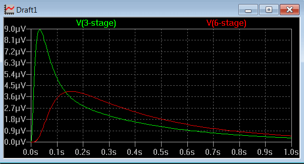
A single pulse when scaled to the output voltage is 30V in amplitude and 62.5 nS wide (1/16MHz). Here is the result at the output for a 3 stage RC filter and a 6 stage RC filter. The input pulse is too short to plot in the graph but it is there at time 0.0:

These waveforms say everything. The worse case noise will be 9uV p-p which means the worse case RMS noise will be around 3uV RMS. If I used a 6 stage filter, you get about half this.
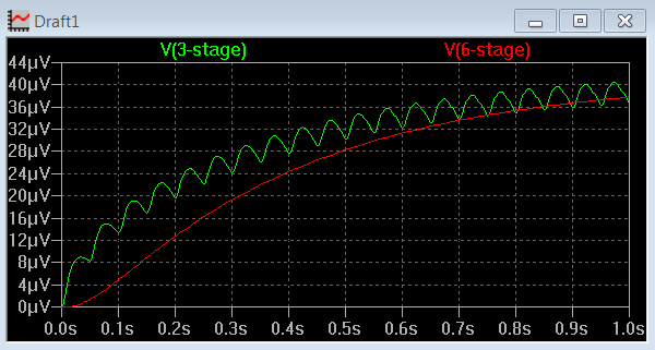
I think the truth is that 9uV of low frequency noise is low enough to be fine - Agilent are proud to boast that their E36xx series supplies have less then 0.35mV of RMS noise. However, all you need to do to reduce the noise further is to control the minimum rate of the error correction. It is a very simple matter of controlling the resolution of the PWM numbers I use. Lets use pulses at 20Hz. you get this:

The 3 stage filter noise has dropped to just over 1uV RMS, and with a 6 stage filter, the noise is essentially gone.
The cost of limiting the minimum correction pulse frequency to 20Hz is that you loose resolution - the smallest adjustment step is 40uV. What is happening is the next correction pulse arrives well before the first has decayed so they combine reducing the peak to peak noise.
I prefer to leave the resolution unlimited, and the user can add a big cap on the supply output terminals if they need lower ripple for some reason. I just think that if you are trying to run a circuit from a power supply that is sensitive to very low frequency noise at the uV level, you will be struggling anyway, particularly if the supply has noise generating microprocessors, a switching pre-regulators, etc.
For people who want minimum noise at the expense of resolution, it is one line of code that needs to be changed.
I could go to a 6 stage filter, but I am not sure it is worth the trouble. I just do not think anyone will notice the difference in reality. With one more capacitor in the gain stage that amplifies the reference output, I can reduce the worse case peak-to-peak noise from 9uV to 5uv and that is probably where I will stop.
It's good enough. It is easy to get carried away with making the numbers look perfect when in reality, it just does not matter. When your load current increases by 1mA, you will get a 9uV+ change anyway due to the resistance of your power leads to the load.
Richard.
EDIT: Thinking about this a bit more, I will limit my resolution to 24 bits. This gives me a minimum adjustment step size of 2uV and the worse case noise will be 7uV p-p. In terms of RMS, it will be more like 1.5uV RMS noise at 1Hz minimum frequency. By setting a minimum frequency for the correction noise, it means that if you needed a super low noise output, add a resistor and capacitor to the output with a time constant over 10 seconds. Going to a 64MHz ATTiny PWM doesn't improve things as much as you would think - you would need 128MHz PWM clock or more to get big improvements. With the ATTiny's 64MHz PWM, I would be worried that jitter might make it worse then the 16MHz Atmega PWM.