I'm making a DDS based function generator (sine and squarewave for something like 50Hz-8MHz). I have the DDS part working and I'm working on the output amplifier section (since the DDS chip outputs around 200mV p-p). The first output amp version I built was actually (unknowingly at the time) based on Dave's schematic (
http://alternatezone.com/electronics/images/DDSFreqGenSchematic.gif )

I used a AD847 for the op-amp but it was way too slow (and I suspect the EL2044/LM6361 will be as well) and got like -20dB attenuation @ 8MHz (due to opamp bandwidth product limit). Well I made a new version with way faster LT1225 op-amps and used two amplifying stages to get around the bandwidth limit problem (then only thing really limiting is the slew rate and these opamps have a pretty good slew rate). Well it's working WAY better but uhh... the problem this time is that the gain actually goes UP with frequency which is uhh sort of baffling
Atm. I have two non-inverting amplifying stages with gain = 5 back-to-back, with a 33k feedback resistor and a 8,2k resistor going to ground from the minus input. Pretty much the same schematic as Dave's. What I'd essentially want is AROUND (its not THAT critical, +-20% is fine with me) 1V p-p from the first amplifying stage and 5V from the second one (I'm going to use an analog multiplexer to select which voltage I want on the output).
Here's a capture of the first stage at 100kHz and everything is working as calculated (Yellow or Vpp(1) is the input and blue or Vpp(2) is the output):

Then at 8MHz gain goes over 8:
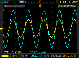
Anybody got any ideas whats happening and what can I do to get rid of it? Only thing I can think of right now is that I'm hitting some resonance and getting extra gain due to that.
Edit: Here's my PCB layout, the two SO-8 up from the lower left corner are the two op-amps:
http://www.dgkelectronics.com/storage/electronics/function_generator/dds_output_layout.png Rest of the stuff isn't even soldered in yet.


