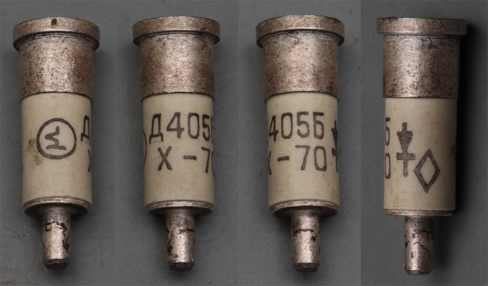
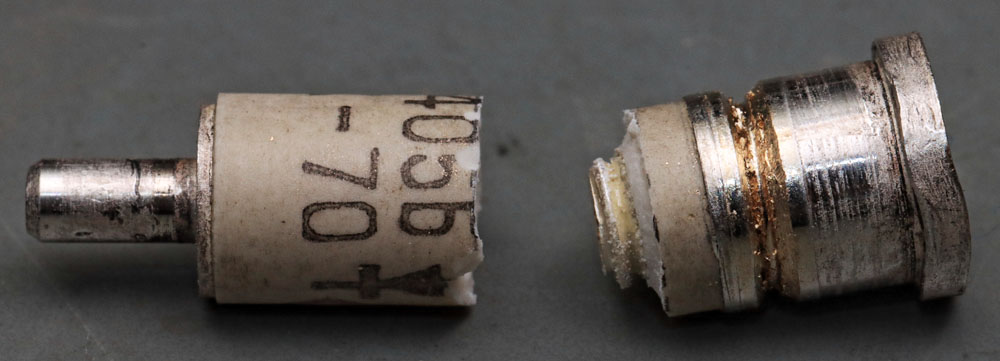
The Д405Б (D405B) is a microwave diode in a cartridge housing. It is a point contact diode. According to the datasheet, it is designed for operation in the wavelength range around 3 cm, which corresponds to a frequency of 10 GHz. The printed logo is reminiscent of the contact wire of a point contact diode and belongs to the Russian factory for semiconductor components Tomilinsky.
The D405 is available with different polarities. In the variant with the additional index П (P), the anode potential is applied to the thinner contact. In the variant without П, the anode potential is applied to the contact with the larger diameter.
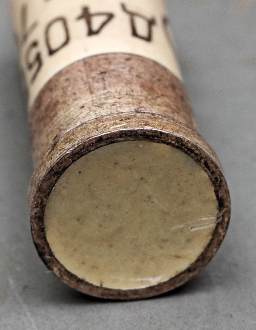
The larger contact is filled with a light-colored potting compound. There is often a screw there, which is also the case here. However, the screw cannot be moved after it has been exposed. The screw was probably glued in, as the housing must be as tight as possible to ensure a long service life.
When I tried to cut off the lower element, the housing broke. Here you can see how far the thread of the lower part protrudes into the ceramic cylinder.
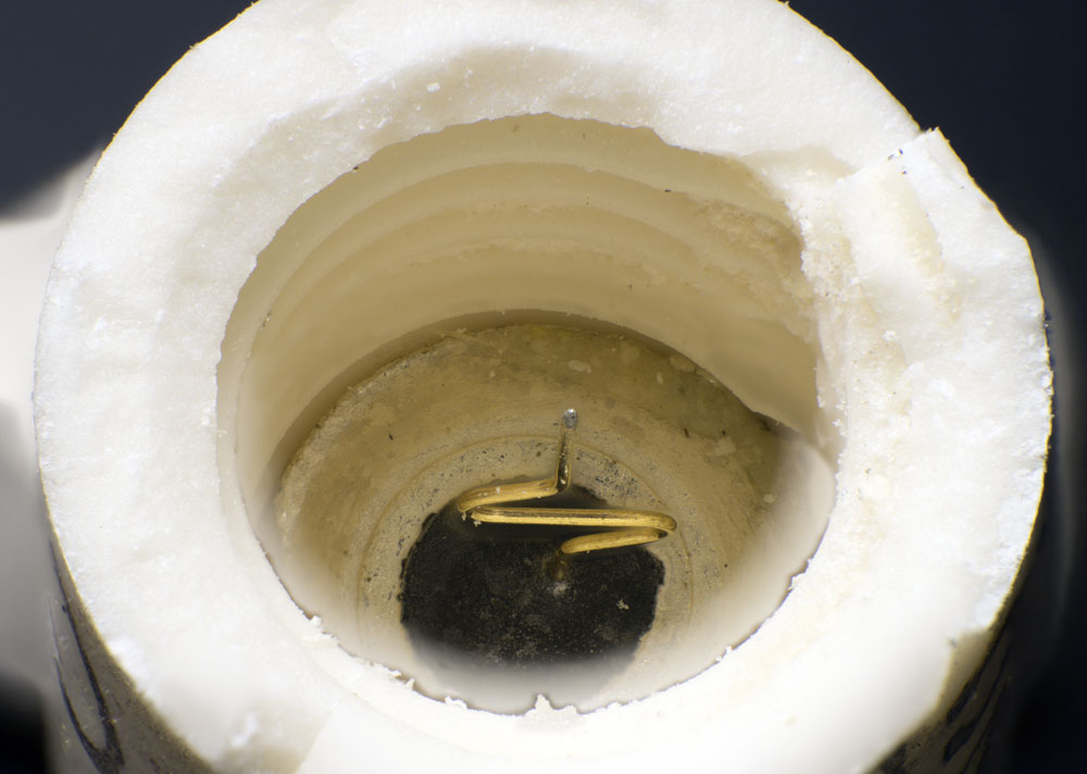
The part with the thinner connection contains the contact wire of the diode.
The thread runs completely through the ceramic cylinder.
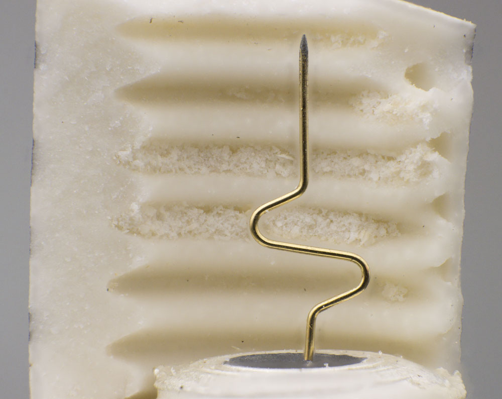
The geometry of the wire provides a certain elasticity, which ensures good contact and at the same time limits the contact pressure to a certain extent.
The wire disappears into a black mass, which probably serves as mechanical stabilization.
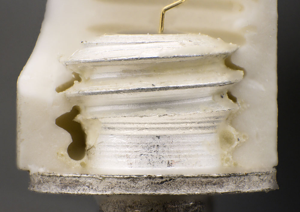
The contact elements are screwed into the ceramic cylinder as far as they will go. The screw in the larger contact can then be used to move the wire and the semiconductor crystal towards each other until the desired contact pressure is achieved. A light-colored material can be seen between the ceramic body and the thread of the contact, which fixes the thread and seals the inside.
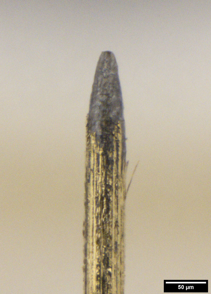
The wire has a diameter of approximately 50µm. At the tip, the diameter is approximately 15µm. The so-called diode bible (Halbleiterdioden - Leitfaden für Erwachsenen-Qualifizierung und Ausbildung im VEB Werk für Fernsehelektronik by Heinz Hornung) states that tungsten or molybdenum or alloys of the two materials are usually used for such high-frequency diodes. The surface was obviously coated with gold. The diode bible further describes that the tips often just have a diameter of 8µm.
Ordinary tip diodes are formed. This involves a relatively high current flowing through the tip contact, which heats up the contact area locally and thus melts it. During this formation, a pn junction is formed and the contact area is mechanically stabilized. More extensive melting produces a higher dielectric strength, which is desirable for conventional diodes such as the OA741 (
https://www.richis-lab.de/Diode05.htm). At the same time, however, the junction capacitance increases. If the diode is to be used at very high frequencies, this is a major disadvantage. The diode bible explains that high-frequency diodes based on gallium arsenide are still formed. High-frequency diodes based on silicon, on the other hand, are usually not formed. The simple contact already provides a sufficient rectification effect. The physical effects that occur at the contact surface are described in more detail with the OA741.
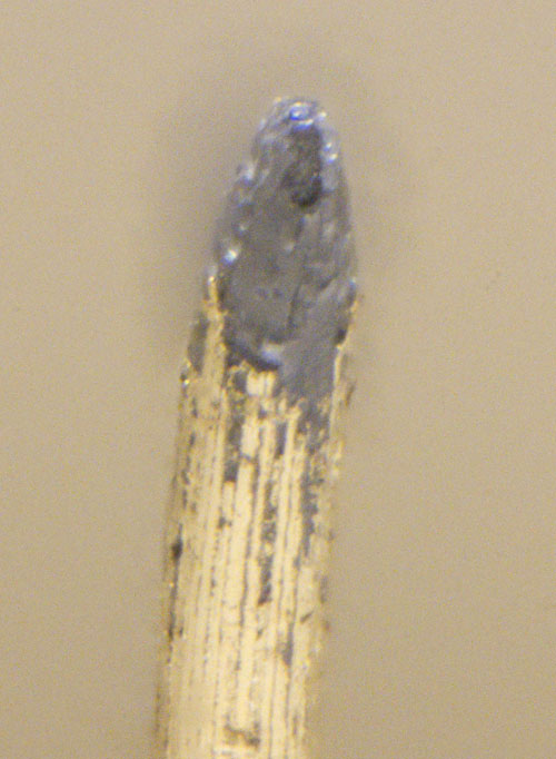
The optical appearance of the wire tip also indicates that no forming took place here. No remnants of a broken connection can be seen. The surface is slightly darker directly at the tip and slightly to the side, but this could have been caused during processing or by the operating current.
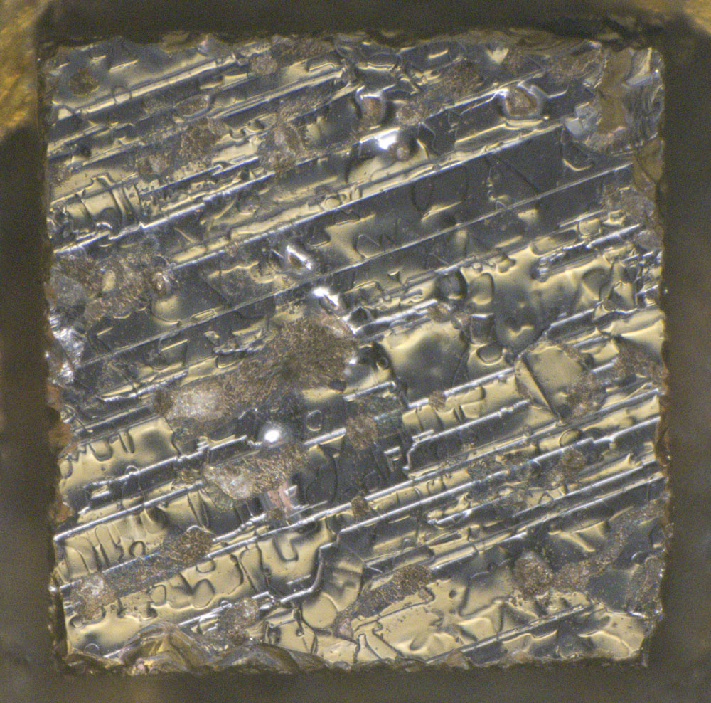
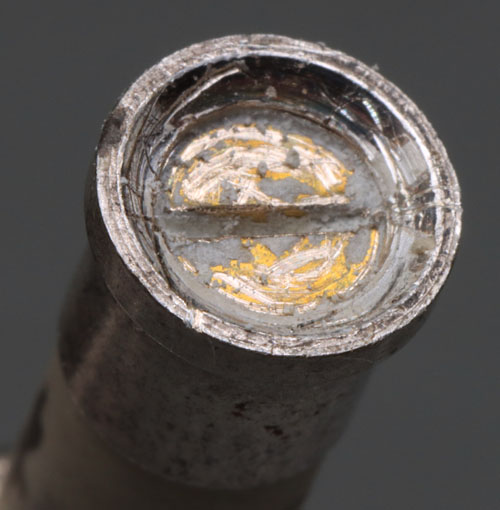
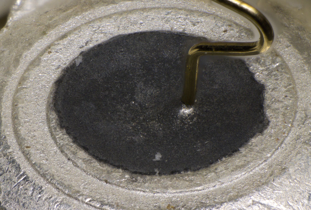
The silicon crystal inside the thicker contact has an edge length of 1 mm.
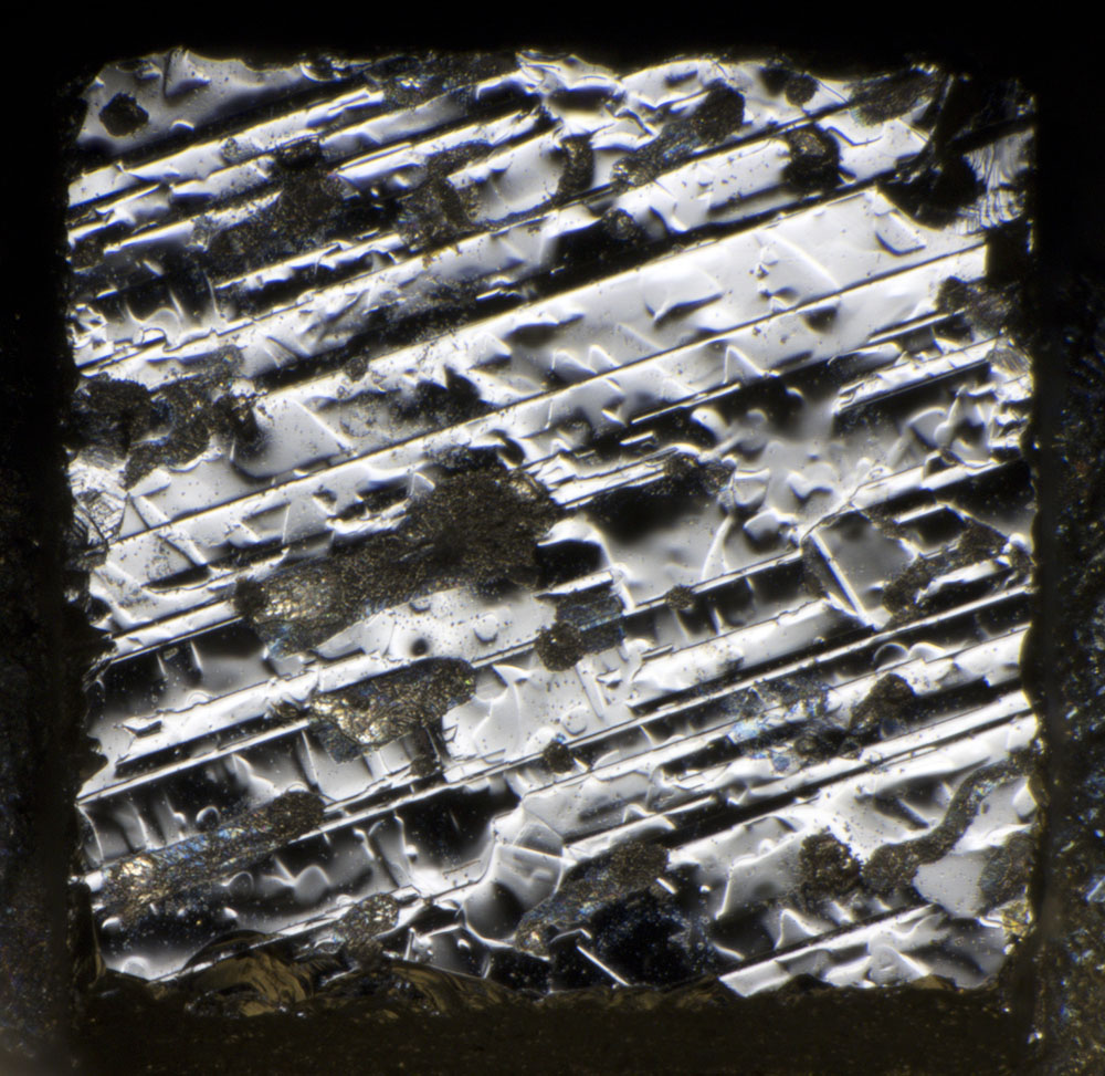
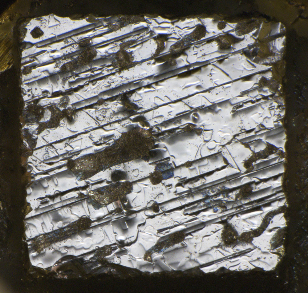
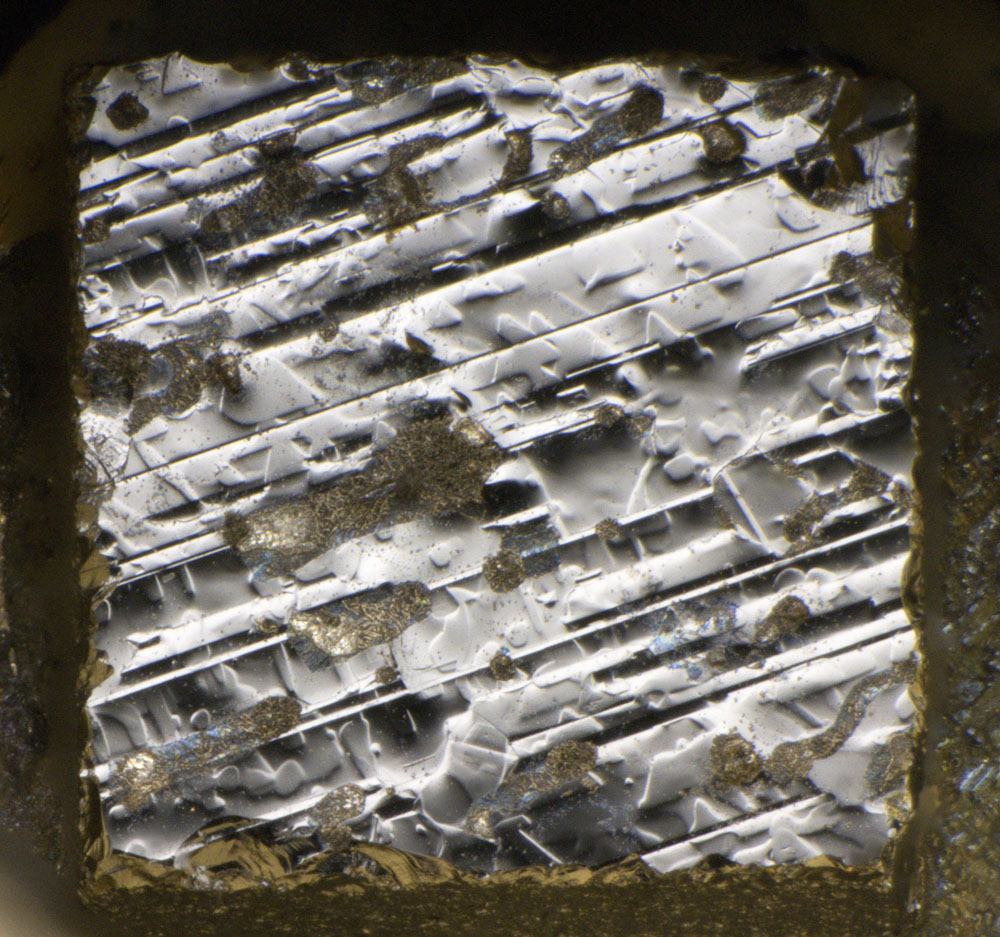
The crystal shows an interesting surface. Different exposures can be used to bring out different characteristics. Dirt has accumulated on the surface. According to the optical appearance, it could be solder.
A contact point with the wire tip is not visible. This also indicates that the diode was not formed.
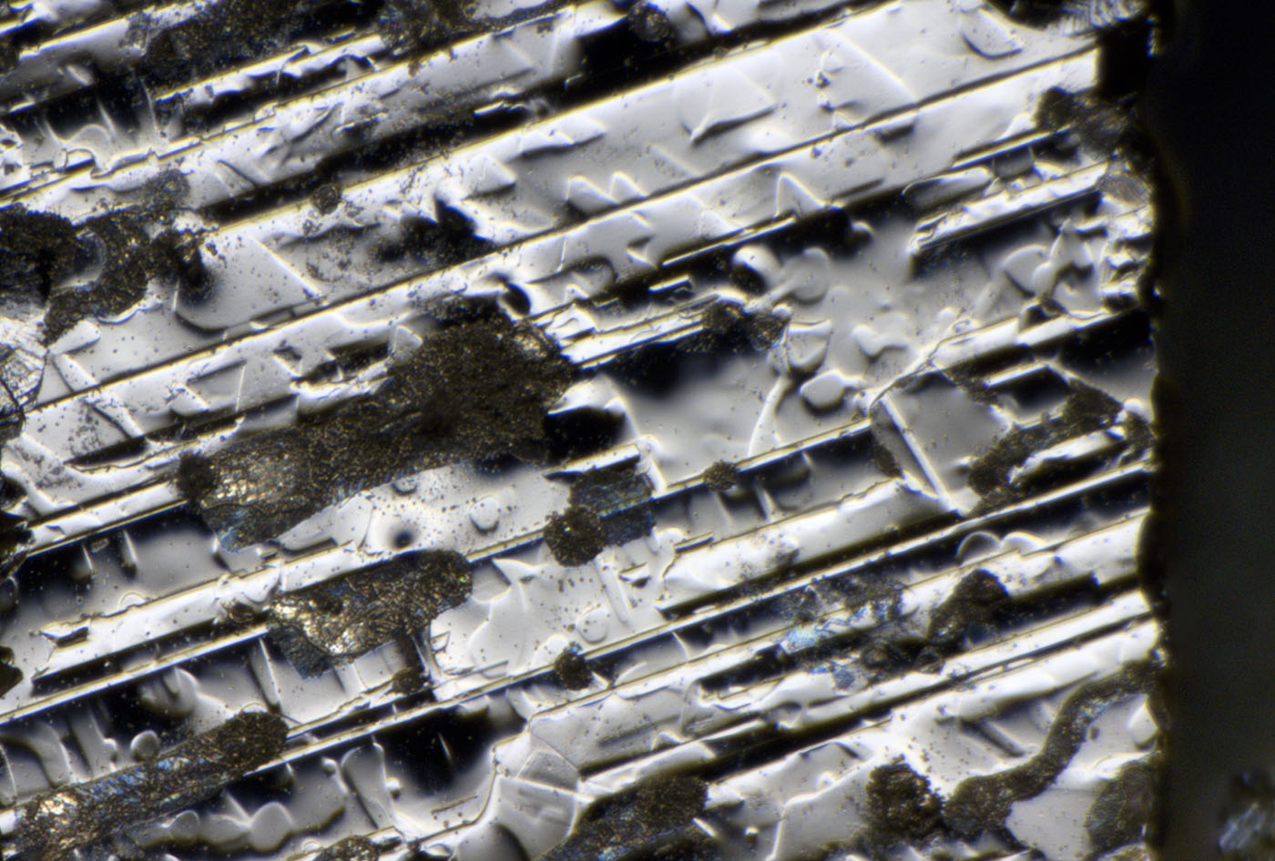
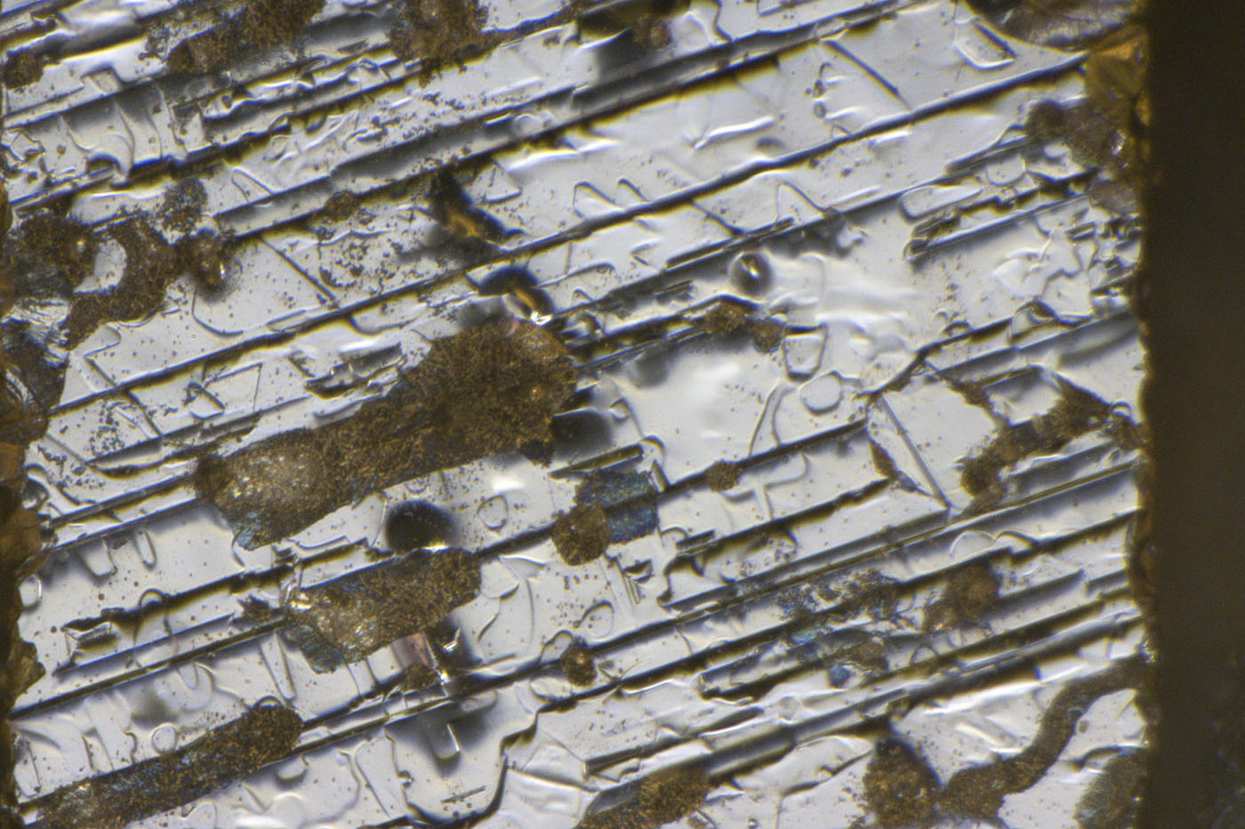
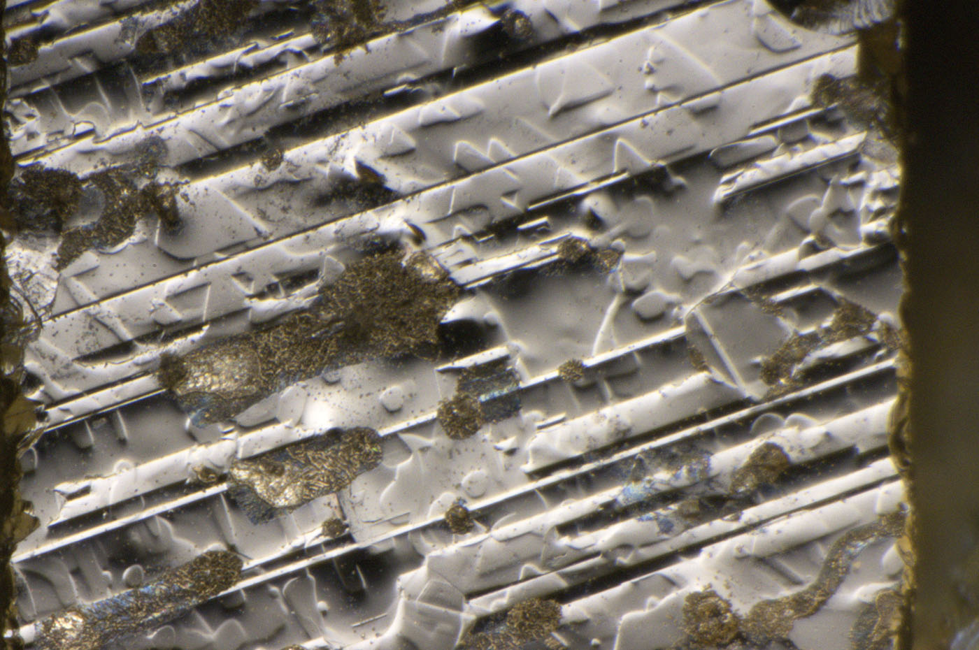
Apart from the "dirt", two different structures are visible on the crystal surface. There are furrows from the top right to the bottom left, as would be expected after mechanical processing. In addition, there are structures that often occur during etching processes. However, these structures are rather irregular here.
https://www.richis-lab.de/Diode13.htm 


