Author Topic: Diodes - die pictures  (Read 21380 times)

0 Members and 1 Guest are viewing this topic.

Offline NoopyTopic starter

  • Super Contributor
  • ***
  • Posts: 1867
  • Country: de
    • Richis-Lab
Diodes - die pictures
« on: June 04, 2021, 11:40:09 am »
In this topic I will post pictures of diodes. You can find the overview here: https://www.richis-lab.de/Diode.htm

I have already a BAV45 (https://www.richis-lab.de/Diode01.htm) and a lot of zenerdiodes in the voltage reference section (https://www.richis-lab.de/REF00.htm).


Today 1N4007, everybody knows it.  :clap: ;D
1000V / 1A


The die is protected with some white potting.


The die is 0,2mm thick.


0,93mm x 0,95mm
Both surfaces are completely covered with tin.


That is an interesting picture. On the side of the die there is an unsteady crossover (upper part is 0,04mm, lower part is 0,13mm). I assume that is the border of an epitaxial layer. I assume there was an n+ wafer then they added an epitaxial n layer to get high voltage ratings and then they added a p layer. Either they diffused the p doping or there was another epitaxial step. At the lower end of the die edge there could be another unsteady crossover. Can´t be sure...  :-/O


https://www.richis-lab.de/Diode02.htm

 :-/O
 
The following users thanked this post: SeanB, doktor pyta, laneboysrc, RoGeorge

Offline RoGeorge

  • Super Contributor
  • ***
  • Posts: 6636
  • Country: ro
Re: Diodes - die pictures
« Reply #1 on: June 04, 2021, 02:56:52 pm »
Thank you, subscribed!   :)
 
The following users thanked this post: Noopy

Online T3sl4co1l

  • Super Contributor
  • ***
  • Posts: 22288
  • Country: us
  • Expert, Analog Electronics, PCB Layout, EMC
    • Seven Transistor Labs
Re: Diodes - die pictures
« Reply #2 on: June 04, 2021, 09:13:46 pm »
Drop it in acid, see if there's any patterning on top?

I suspect old diodes like those, won't have much (probably just guard rings?), but some power schottky are made with fine cells like MOSFETs. Should be interesting to see.

Tim
Seven Transistor Labs, LLC
Electronic design, from concept to prototype.
Bringing a project to life?  Send me a message!
 

Offline NoopyTopic starter

  • Super Contributor
  • ***
  • Posts: 1867
  • Country: de
    • Richis-Lab
Re: Diodes - die pictures
« Reply #3 on: June 05, 2021, 12:24:46 am »
Drop it in acid, see if there's any patterning on top?

Good idea!  :-+ Unfortunately I have lost the die. ::) Will have to decap one more 1N4007.


I suspect old diodes like those, won't have much (probably just guard rings?), but some power schottky are made with fine cells like MOSFETs. Should be interesting to see.

I´m pretty sure the 1N4007 has nothing like that.
I have taken pictures of two IGBTs and their freewheeling diodes:


International Rectifier IRG4PH40K
https://www.richis-lab.de/Bipolar35.htm


IXYS IXGH48N60C3D1
https://www.richis-lab.de/Bipolar26.htm


And of course the darlington power modules:


Powerex KD324510
https://www.richis-lab.de/Bipolar19.htm


Gleichrichterwerk Stahnsdorf SU510
https://www.richis-lab.de/Bipolar24.htm


But I will have to get a power schottky...  :-/O ;D

Offline David Hess

  • Super Contributor
  • ***
  • Posts: 17065
  • Country: us
  • DavidH
Re: Diodes - die pictures
« Reply #4 on: June 05, 2021, 02:32:12 am »
High voltage diodes like the 1N4007 usually have a PIN structure but I do not know that it will be apparent.  They can work in place of dedicated RF PIN diodes.
 
The following users thanked this post: RoGeorge

Offline NoopyTopic starter

  • Super Contributor
  • ***
  • Posts: 1867
  • Country: de
    • Richis-Lab
Re: Diodes - die pictures
« Reply #5 on: June 05, 2021, 06:12:54 am »
High voltage diodes like the 1N4007 usually have a PIN structure but I do not know that it will be apparent.  They can work in place of dedicated RF PIN diodes.

That is what I wanted to say with the epitaxial n layer. As far as I'm informed the i-region often is not intrinsic but ligthly n-doped.

I'm not sure about the visual aspect either. In theory the crystal junction shouldn't be visible but in practice the world often isn't perfect.
I don't think the crossover is caused by the die separation. It's too unsteady.

Offline NoopyTopic starter

  • Super Contributor
  • ***
  • Posts: 1867
  • Country: de
    • Richis-Lab
Re: Diodes - die pictures
« Reply #6 on: July 22, 2021, 07:33:55 pm »


exe wanted to see a FERD (Field Effect Rectifier Diode). Finally I have taken some pictures of a ST Microelectronics FD40H100.


The die is connected with four quite big bondwires and the die is 0,2mm thick.
I killed round about ten diodes to get one complete die! After burning the epoxy the remaining stuff is still quite stiff. It seems like the die is desoldered and lifted a little while being in the furnance. When you remove the package remainings the bondwires tend to break the die.  |O


3,8mm x 3,4mm


The metal layer is very clean. You see no structures except a trench at the edge of the die.
But let´s remove the metal layer...  :-/O


Hey, there are more structures! I don´t think they planed the surfaces. I assume the metal layer is thick enough to cover the unevenness.
In a power MOSFET you often find small square transistors (https://www.richis-lab.de/FET07.htm) or thin transistor stripes (https://www.richis-lab.de/FET15.htm). Here it looks like we have staircase-shaped MOSFETs with quite big structures.


I assume the bright parts are contact areas to the metal layer.


It looks like the other "staircases" are the gate areas connected to the frame of the structure.


That sound reasonable: Source is connected over a large area and gate is connected around the frame of the structure.


https://www.richis-lab.de/Diode03.htm

 :-/O
 
The following users thanked this post: doktor pyta, exe, RoGeorge, Miyuki

Offline NoopyTopic starter

  • Super Contributor
  • ***
  • Posts: 1867
  • Country: de
    • Richis-Lab
Re: Diodes - die pictures
« Reply #7 on: August 05, 2021, 04:10:38 am »


Diotec BY550-50, a standard rectifier that can conduct up to 5A and block up to 50V. There are bigger versions blocking up to 1000V.


That looks quite similar to the 1N4007 but there are additional metal discs between the die and the contacts.


The edge length of the die is 2,3mm. That gives you 0,95A/mm² while the 1N4007 works with 1,13A/mm².


The die is 0,26mm thick and seems to consist of two layers (0,06mm/0,20mm). Probably the die is manufactured epitaxial.


https://www.richis-lab.de/Diode04.htm

 :-/O
 
The following users thanked this post: RoGeorge

Offline Miyuki

  • Frequent Contributor
  • **
  • Posts: 907
  • Country: cz
    • Me on youtube
Re: Diodes - die pictures
« Reply #8 on: August 05, 2021, 07:34:39 am »
exe wanted to see a FERD (Field Effect Rectifier Diode). Finally I have taken some pictures of a ST Microelectronics FD40H100.
Interesting stuff to see, thanks 🖤
I just wonder why even ST did not tell switching characteristics in the datasheet. Are they so ashamed of how bad it really is?
 

Offline NoopyTopic starter

  • Super Contributor
  • ***
  • Posts: 1867
  • Country: de
    • Richis-Lab
Re: Diodes - die pictures
« Reply #9 on: August 05, 2021, 08:14:52 am »
exe wanted to see a FERD (Field Effect Rectifier Diode). Finally I have taken some pictures of a ST Microelectronics FD40H100.
Interesting stuff to see, thanks 🖤
I just wonder why even ST did not tell switching characteristics in the datasheet. Are they so ashamed of how bad it really is?

It is a pleasure! I have some more interesting diodes here... ...more interesting than the 1N4007.  :-/O

Yeah, it seems the switching characteristic of the FERD is nothing you want to promote.  ;D


Offline NoopyTopic starter

  • Super Contributor
  • ***
  • Posts: 1867
  • Country: de
    • Richis-Lab
Re: Diodes - die pictures
« Reply #10 on: December 05, 2021, 04:47:40 am »


We need pictures of a point-contact diode! Let´s take a look into a OA741 built by the Werk für Fernsehelektronik Berlin.


You can scrape off the label.


One of the connection pins is surrounded by solder, on which a thin germanium crystal is located. A gold wire contacts the crystal from above. The curve described by the wire ensures that the wire maintains contact with the crystal during production.
The tip diode is a Schottky diode. The active area results from the contact of the metallic tip with the semiconductor material. Ultimately this is an advancement of the open crystal detectors used as demodulators in old radio receivers.


The crystal is about 80µm thick. The edge length is 1,3mm. The special surface structure resulted from the etching process which was used to remove imperfections from the surface of the crystal.


The gold wire has a diameter of about 0.04mm. It is fused with the semiconductor crystal. To fuse the wire a high current is conducted through the diode which strongly heats the junction. Even without a fused contact a Shottky diode junction is formed at the contact point of the gold wire but the stability and current-carrying capacity are lower. Point-contact diodes that are not welded however offer lower junction capacitances which is why they are used as HF diodes.


https://www.richis-lab.de/Diode05.htm

 :-/O
 
The following users thanked this post: edavid, doktor pyta, RoGeorge, Miyuki, horo, Dabbot

Offline RoGeorge

  • Super Contributor
  • ***
  • Posts: 6636
  • Country: ro
Re: Diodes - die pictures
« Reply #11 on: December 05, 2021, 11:16:01 am »
What's all those triangle-shaped bumps on the Ge crystal?
Isn't the surface supposed to be mirror clean, like a Si wafer?

Offline NoopyTopic starter

  • Super Contributor
  • ***
  • Posts: 1867
  • Country: de
    • Richis-Lab
Re: Diodes - die pictures
« Reply #12 on: December 05, 2021, 11:21:52 am »
Back in the days the etching process wasn't as good as today. But it was ok. Eventually the diode is just were the gold wire is welded onto the crystal that was quite a rude process/diode type.  ;D

Edit: But to be honest I don't know where the structure comes from. Crystal lattice?
« Last Edit: December 05, 2021, 11:25:13 am by Noopy »
 

Online T3sl4co1l

  • Super Contributor
  • ***
  • Posts: 22288
  • Country: us
  • Expert, Analog Electronics, PCB Layout, EMC
    • Seven Transistor Labs
Re: Diodes - die pictures
« Reply #13 on: December 05, 2021, 04:37:21 pm »
I would guess potassium hydroxide etch, it's anisotropic at least in silicon, tending to make pyramidal pits -- with respect to whatever crystal plane is commonly used, of course.  If that's the case, then it appears they:
1. Cut along a crystal plane parallel to one of those pyramid faces,
2. Etched long enough that the pit size became quite exaggerated, enough to see on magnification.

And if that's all the case, apparently also the etching process doesn't interrupt itself, so tends to maintain the faceted appearance?

Were those awfully rugged, then?  I can't imagine e.g. dumping a capacitor into a common diode today and getting anything but a short circuit (or an open circuit, at higher energy levels).  I suppose a schottky junction is still a short circuit, of sorts, but a practical one as it just so happens! :-DD

Tim
Seven Transistor Labs, LLC
Electronic design, from concept to prototype.
Bringing a project to life?  Send me a message!
 
The following users thanked this post: Noopy

Offline NoopyTopic starter

  • Super Contributor
  • ***
  • Posts: 1867
  • Country: de
    • Richis-Lab
Re: Diodes - die pictures
« Reply #14 on: December 05, 2021, 04:54:36 pm »
Well these point contact diodes were rugged with respect to the open crystal detectors in the old radios.  ;D

It´s interesting that science isn´t sure about the nature of these fused junction:
Some state the tip forms a p-junction. But gold is nothing to dope germanium so that doesn´t sound reasonable.
Some state the melting and recrystallization develops p-doping. But no one explains how that should be possible.
Some state it´s still a Schottky junction. That´s also my opinion.  :-+

Offline NoopyTopic starter

  • Super Contributor
  • ***
  • Posts: 1867
  • Country: de
    • Richis-Lab
Re: Diodes - die pictures
« Reply #15 on: December 05, 2021, 09:51:29 pm »
I got a special teaching document used in the Werk für Fernsehelektronik which explains these point contact diodes and now I have to correct myself:

It seems like the welding of the gold wire really generates a p-doped area in the n-doped crystal. I still don´t understand how that works on an atomic level.  :-//

In addition the document describes that they added 1% gallium to the gold wire. The gallium diffuses into the germanium and gives you an additional p-doping.


BTW: The document describes two types of etching agents for cleaning the germanium surface:
- nitric acid, hydrofluoric acid, acetic acid and potassium bromide
- hydrogen peroxide, hydrofluoric acid and deionized water
Doesn´t sound healthy like always in the semiconductor industry.  >:D

Offline Gyro

  • Super Contributor
  • ***
  • Posts: 9880
  • Country: gb
Re: Diodes - die pictures
« Reply #16 on: December 05, 2021, 10:24:17 pm »
...
The gold wire has a diameter of about 0.04mm. It is fused with the semiconductor crystal. To fuse the wire a high current is conducted through the diode which strongly heats the junction. Even without a fused contact a Shottky diode junction is formed at the contact point of the gold wire but the stability and current-carrying capacity are lower. Point-contact diodes that are not welded however offer lower junction capacitances which is why they are used as HF diodes.

This puts me in mind of a very old article (maybe an early Practical Wireless) on constructing your own transistor.

Irrc, it used a small ebonite knob as the basic framework, and the guts from two Germanium point contact diodes. Both diodes were carefully cracked open and the crystal and lead of one of them glued into the centre hole, the wire being the base connection. The two other leads, with their point contact wires still attached were then screw tag attached at each side of the hole and bent so that their point contacts were brought into spring contact with the surface of the Germanium crystal - as close together as possible and physically separated by a thin sliver of Mica, again glued to the edge of the hole.

I don't remember the 'forming' details clearly, but it involved passing current through one of the point contact wires until it reached red heat, presumably locally modifying the doping of the crystal to some fairly shallow depth. Irrc, this process was repeated several times until the desired (some?) gain, ... or total failure, was achieved.

I don't remember the year of the article, but it must have been at the point where transistors were rather expensive relative to Germanium diodes... or it was for masochistic readers!

I'd love to find the article again. Maybe it's hidden away somewhere in the americanradiohistory archive - if I had a better idea where to look.
Best Regards, Chris
 

Online T3sl4co1l

  • Super Contributor
  • ***
  • Posts: 22288
  • Country: us
  • Expert, Analog Electronics, PCB Layout, EMC
    • Seven Transistor Labs
Re: Diodes - die pictures
« Reply #17 on: December 06, 2021, 06:24:49 am »
Gold shouldn't do anything by itself, other than kill carrier lifetime I think (at least, that's the effect in Si), which probably doesn't have much effect here other than perhaps reducing the reverse breakdown voltage.  Some germanium will end up alloyed into it I think, but that's not very important, it'll still be largely metallic.

Gallium, that makes sense.  And it doesn't take much, so yeah.

Oh wait, for schottky diodes, all that's needed is a doped substrate -- the contact potential with the metal is what makes the diode, doping isn't needed.  Well, interesting then that the above could perhaps make a junction diode, albeit a rather thin one I think (given the heavy doping and short diffusion time)?

I've certainly heard of alloy diodes/transistors -- using a whole blob of In, but not of using alloys in turn to do it.

Tim
Seven Transistor Labs, LLC
Electronic design, from concept to prototype.
Bringing a project to life?  Send me a message!
 

Offline NoopyTopic starter

  • Super Contributor
  • ***
  • Posts: 1867
  • Country: de
    • Richis-Lab
Re: Diodes - die pictures
« Reply #18 on: December 06, 2021, 07:04:17 am »
This puts me in mind of a very old article (maybe an early Practical Wireless) on constructing your own transistor.
...

I have read similar stories.  :-+


Oh wait, for schottky diodes, all that's needed is a doped substrate -- the contact potential with the metal is what makes the diode, doping isn't needed.

Yes, without welding the parts together you have some kind of schottky diode.  :-+


Well, interesting then that the above could perhaps make a junction diode, albeit a rather thin one I think (given the heavy doping and short diffusion time)?

A thin one, yes.
The document I have here states that the welding process was done with 0,6A-1,2A for 0,2s.

Online BrokenYugo

  • Super Contributor
  • ***
  • Posts: 1188
  • Country: us
Re: Diodes - die pictures
« Reply #19 on: December 12, 2021, 08:17:05 pm »
...
The gold wire has a diameter of about 0.04mm. It is fused with the semiconductor crystal. To fuse the wire a high current is conducted through the diode which strongly heats the junction. Even without a fused contact a Shottky diode junction is formed at the contact point of the gold wire but the stability and current-carrying capacity are lower. Point-contact diodes that are not welded however offer lower junction capacitances which is why they are used as HF diodes.

This puts me in mind of a very old article (maybe an early Practical Wireless) on constructing your own transistor.

Irrc, it used a small ebonite knob as the basic framework, and the guts from two Germanium point contact diodes. Both diodes were carefully cracked open and the crystal and lead of one of them glued into the centre hole, the wire being the base connection. The two other leads, with their point contact wires still attached were then screw tag attached at each side of the hole and bent so that their point contacts were brought into spring contact with the surface of the Germanium crystal - as close together as possible and physically separated by a thin sliver of Mica, again glued to the edge of the hole.

I don't remember the 'forming' details clearly, but it involved passing current through one of the point contact wires until it reached red heat, presumably locally modifying the doping of the crystal to some fairly shallow depth. Irrc, this process was repeated several times until the desired (some?) gain, ... or total failure, was achieved.

I don't remember the year of the article, but it must have been at the point where transistors were rather expensive relative to Germanium diodes... or it was for masochistic readers!

I'd love to find the article again. Maybe it's hidden away somewhere in the americanradiohistory archive - if I had a better idea where to look.

I've seen it before to and tracked it down, January 1954 issue. Good scan here: http://www.douglas-self.com/ampins/wwarchive/wwarchive.htm#home

Whole magazine scan here: https://worldradiohistory.com/UK/Wireless-World/50s/Wireless-World-1954-01-S-OCR.pdf article on PDF page 24.
 
The following users thanked this post: Gyro, RoGeorge, Noopy

Offline Gyro

  • Super Contributor
  • ***
  • Posts: 9880
  • Country: gb
Re: Diodes - die pictures
« Reply #20 on: December 12, 2021, 08:52:01 pm »
Thank you! It's ages since I last saw that (in paper form from a long dead neighbour!) - quite nostalgic.
« Last Edit: December 12, 2021, 10:16:02 pm by Gyro »
Best Regards, Chris
 

Offline NoopyTopic starter

  • Super Contributor
  • ***
  • Posts: 1867
  • Country: de
    • Richis-Lab
Re: Diodes - die pictures
« Reply #21 on: February 09, 2022, 11:19:37 am »


We had the gold wire point-contact diode OA741 (https://www.richis-lab.de/Diode05.htm) now let´s take a look into a tungsten wire point-contact diode.

Here we have a  Д2Ж (D2Ž) built in the semiconductor plant Novosibirsk. The family D2 contains seven variants, the D2Ž has the highest breakdown voltage of 150V. The leakage current is 0,25mA. The maximum mean current flow is 8mA. The maximum peak current is 25mA.


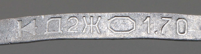
On the contact sheet there is a diode showing the current flow direction, the name Д2Ж and the logo of the semiconductor plant Novosibirsk. I don´t know what 1.70 means.


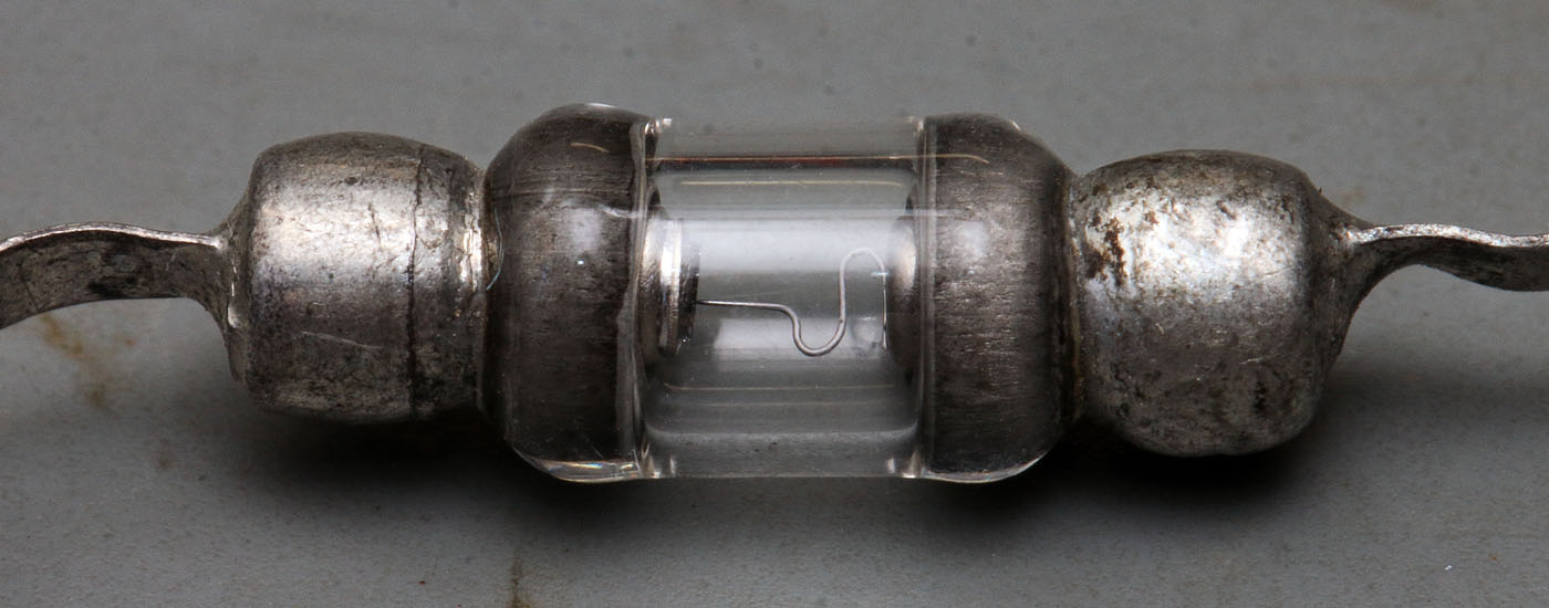
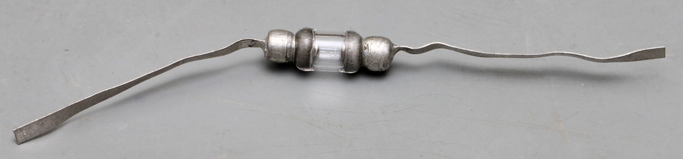
It´s a glass housing with metal caps at both ends.


The wire colour shows that it isn´t gold but probably tungsten. Sometimes the tungsten contains some dopant like aluminium.

For proper pictures a higher glass uniformity would be nice.  ;D


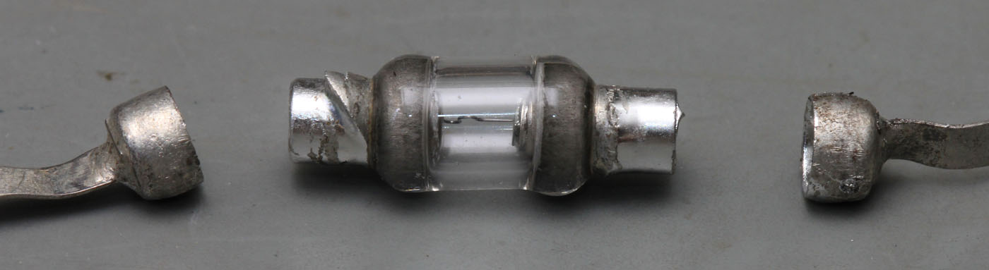
You can remove the caps at the ends. Under the caps there are shells in which they pushed cylinders carrying the germanium die and the point contact wire.


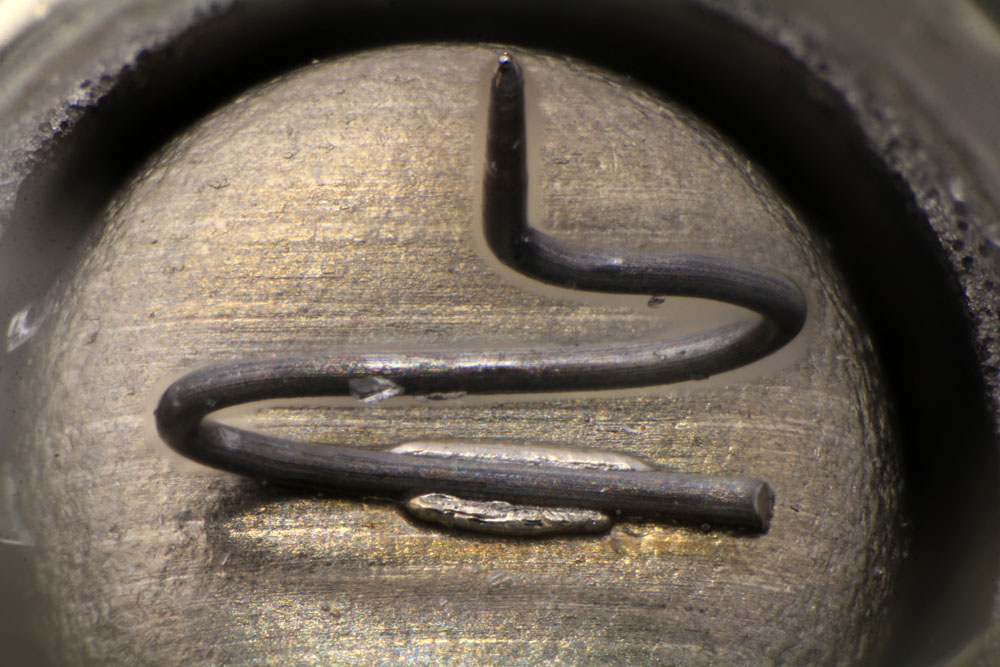
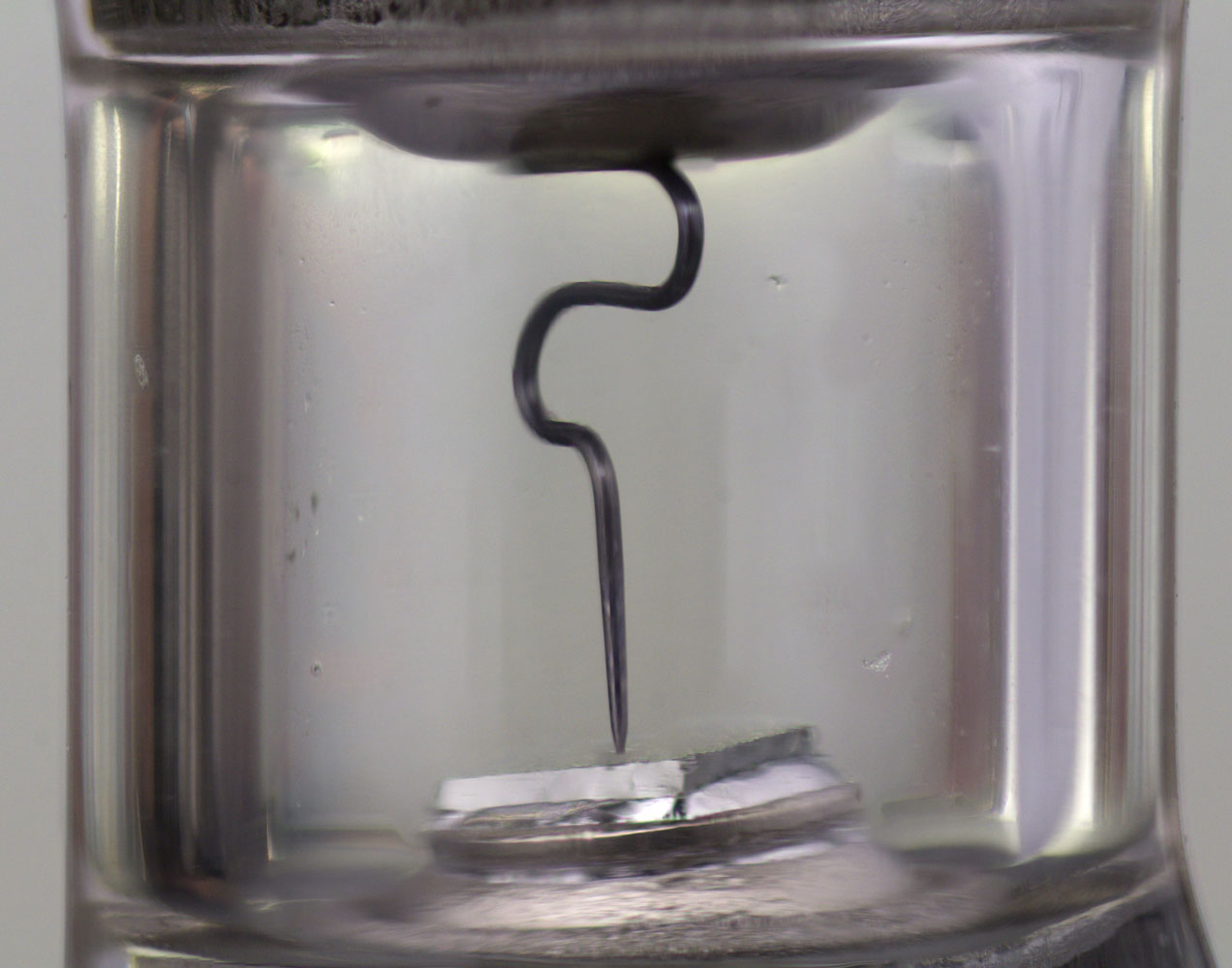
The geometry of the wire guarantees a spring effect pushing the wire onto the die and compensating different thermal expansion.


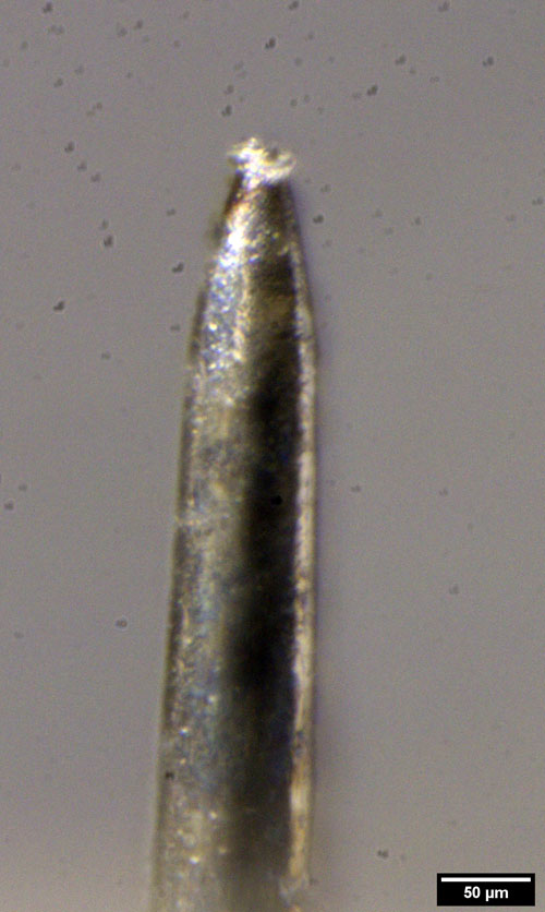
The tip of the wire is round about 30µm in diameter.


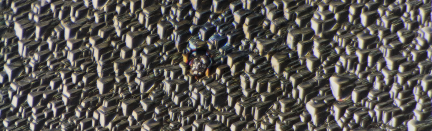
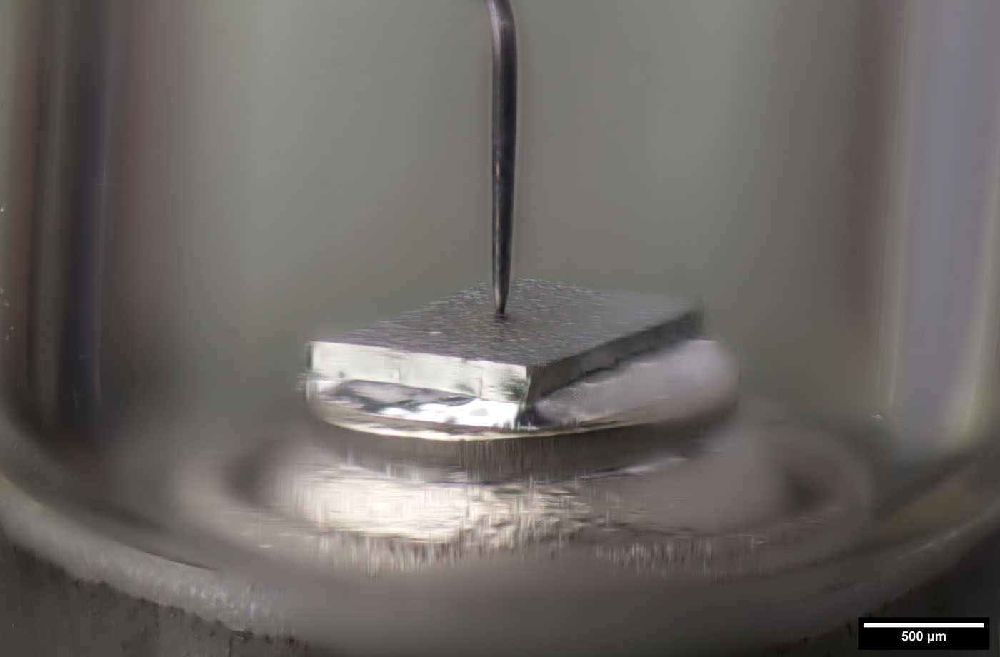
The edge length of the die is 1,2mm. The structure on the surface is formed while the impurities are etched away.

The wire was fused to the die. You can clearly see the molten germanium and the discoloration due to the heat generated in this process.


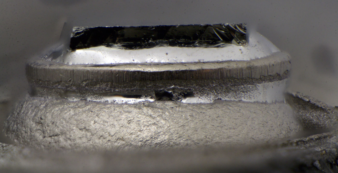
The die is at least 200µm thick while the die in the OA741 was just 80µm thick. Perhaps that is due to the different voltage ratings (40V vs. 150V).

The die sits on a round carrier that is put on the cylinder sitting in one of the shells of the package.


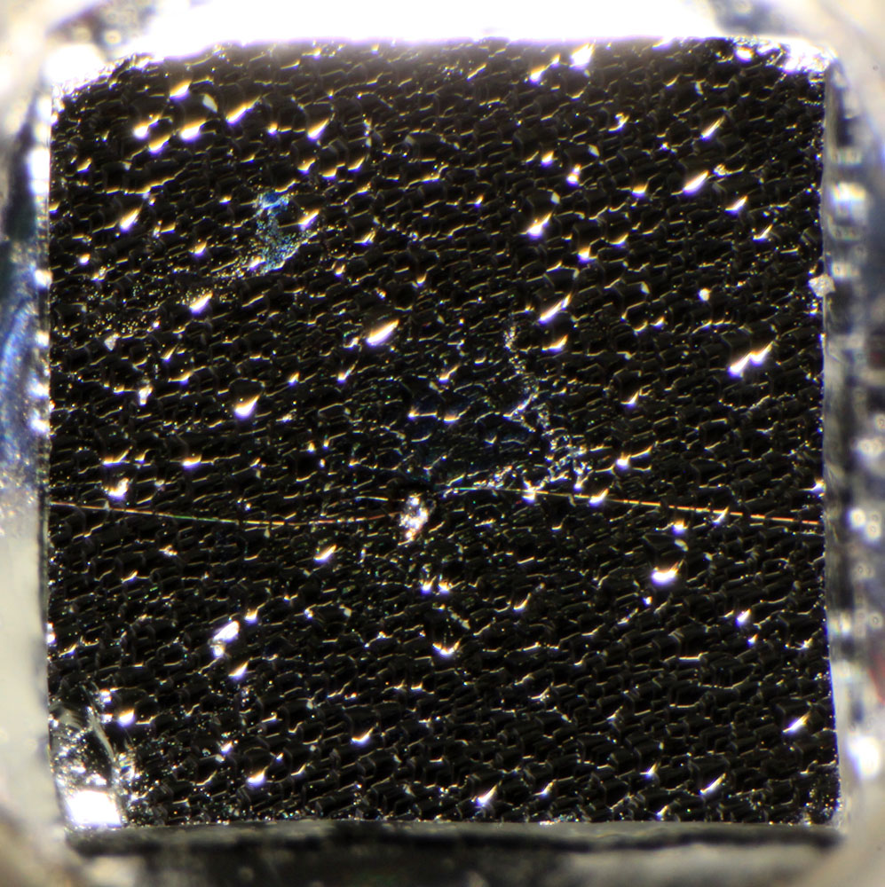
There is a crack going from one side of the die to the other. Since the diode wasn´t in use it seems like the fuse process cracked the die due to the heat exposure.


https://www.richis-lab.de/Diode06.htm

 :-/O
 
The following users thanked this post: SeanB, TurboTom, Gyro, RoGeorge, Miyuki, serg-el

Offline serg-el

  • Regular Contributor
  • *
  • Posts: 143
  • Country: ru
Re: Diodes - die pictures
« Reply #22 on: February 10, 2022, 10:21:30 am »
I don´t know what 1.70 means.

Date of manufacture.
January 1970

http://www.155la3.ru/d2.htm
 
The following users thanked this post: RoGeorge, Miyuki, horo, Noopy

Offline NoopyTopic starter

  • Super Contributor
  • ***
  • Posts: 1867
  • Country: de
    • Richis-Lab
Re: Diodes - die pictures
« Reply #23 on: February 10, 2022, 06:45:14 pm »

Offline exe

  • Supporter
  • ****
  • Posts: 2607
  • Country: nl
  • self-educated hobbyist
Re: Diodes - die pictures
« Reply #24 on: February 18, 2022, 12:30:40 pm »
exe wanted to see a FERD (Field Effect Rectifier Diode). Finally I have taken some pictures of a ST Microelectronics FD40H100.
Interesting stuff to see, thanks 🖤
I just wonder why even ST did not tell switching characteristics in the datasheet. Are they so ashamed of how bad it really is?

It is a pleasure! I have some more interesting diodes here... ...more interesting than the 1N4007.  :-/O

Yeah, it seems the switching characteristic of the FERD is nothing you want to promote.  ;D

Hi there! FERD diodes are marketed as energy-efficient solution for switching regulators. Unfortunately, there is actual data on switching performance. I could only find on ST's website a comment from an ST's employee that they reasonably fast because they don't have pn junction, and they are more like schottky or mosfets or something like that (again, no specific numbers). I'm a big fan of FERD diodes, and I wanted to know the numbers. So, I decided to measure it myself.

The setup is the following: AD2 generates bipolar square wave (+-1V), which is passed through the DUT (diode under test, haha) and 100 Ohm resistor. The yellow trace is from the siggen, the blue one is voltage across the resistor. The recovery is the positive spike on blue trace (ideally there should be none).

As we can see, FERD diodes are significantly faster than 1n4004 (I measured FERD40U50CFP and FERD60M45CT). But there is one thing that troubles me. It seems on switching edges the voltage across resistor can exceed output of signal gen. I wonder if that is due to parasitic inductance. Unfortunately, I don't have shorter cables ready at hand, but let me know if it makes sense to re-do measurements with shorter cables.

To confirm that I'm measuring recovery time and not something else, I also measured BAT41. It showed virtually no recovery. That small spike could be inductive kickback or something. After doing all the measurement I also tried MBR745, which is shottkey. And, guess what, I see some "recovery" on the plot. It's nowhere near as bad but still noticeable. I was puzzled.

But then I realized that power diodes have quite some capacitance. So, I put back my trusty BAT41 and added 1n cap. Guess what, it started to look like MBR745 (1n is datasheet value for diode capacitance). With 3n cap (capacitance of FERD diodes) the waveform looked like a FERD diode in terms of "recovery".

So, I'd say FERD diodes are fast, but have significant capacitance.
 
The following users thanked this post: edavid, Noopy


Share me

Digg  Facebook  SlashDot  Delicious  Technorati  Twitter  Google  Yahoo
Smf