Author Topic: DACs - die pictures  (Read 27293 times)

0 Members and 8 Guests are viewing this topic.

Online mawyatt

  • Super Contributor
  • ***
  • Posts: 3455
  • Country: us
Re: DACs - die pictures
« Reply #100 on: July 06, 2022, 04:01:21 pm »
We utilized a bunch of these back in the day, brings back fond memories. Thanks for posting and showing the images.

Great work  :-+

Best,
Curiosity killed the cat, also depleted my wallet!
~Wyatt Labs by Mike~
 

Offline NoopyTopic starter

  • Super Contributor
  • ***
  • Posts: 1816
  • Country: de
    • Richis-Lab
Re: DACs - die pictures
« Reply #101 on: July 06, 2022, 04:43:34 pm »
Thanks!  :-+A
It was a pleasure for me.

Spoiler: The AD562 and the six parts prior to it belong to a bigger module... ;)

Offline NoopyTopic starter

  • Super Contributor
  • ***
  • Posts: 1816
  • Country: de
    • Richis-Lab
Re: DACs - die pictures
« Reply #102 on: August 01, 2022, 03:51:34 pm »


The Micro Power Systems MP7616 is a low-cost 16bit DAC designed primarily for HIFI applications. In this area nonlinearity is less problematic. The datasheet specifies a typical nonlinearity of 0,01% (12bit) and a differential nonlinearity of 0,006% (13bit). In addition there is a gain factor error of +/-0,8%. The output settles within +/-0.011% in 2µs.

Exar took over Micro Power Systems in 1994 and continued to produce the MP7616.


The datasheet contains a block diagram. Reference voltage source and output operational amplifier must be added externally. The basis is a 12Bit-DAC. To extend this DAC to 16Bit at low cost, instead of four binary controlled current sources, 15 current sources were integrated which realize the 16 steps of the 4MSB. The values of these resistors and the corresponding current switches have to be set much less precisely this way. The Exar datasheet advertises an increase of the permissible inaccuracy from 0.0015% to 0.024%, which made it possible to go without a laser adjustment of the resistors.


The die of the MP7616 is 3,4mm x 2,5mm.


At the upper edge of the die you find the designation 7616.


The Micro Power Systems logo is shown on the lower edge. In addition, 8 masks and the string 6DSRCA are integrated there. A pattern of squares makes it possible to evaluate the alignment of the masks.

Different transistors can be measured in the three test structures TD1, TD2 and TD3. Each block seems to contain two transistors, probably a p- and an n-channel MOSFET. It looks like there are different channel widths in the three test structures.


Another test structure is integrated at the left edge of the die.


A structure in the lower left corner of the die shows the performance of the manufacturing process. The lowest elements are 4µm in high.  8)


In the GDR, in the "Zentrum Wissenschaft und Technik", the MP7616 was analyzed in detail. As described in the context of the HFO TF536 (https://www.richis-lab.de/DAC09.htm), the GDR urgently needed its own 16Bit-DAC. The results of the MP7616 analysis are documented here:
Part 1 (17MB): https://www.richis-lab.de/images/DAC/24x14.pdf
Part 2 (4MB): https://www.richis-lab.de/images/DAC/24x15.pdf


The die documented at the "Zentrum Wissenschaft und Technik" shows no functional difference from the circuit we have here. Only the A at the end of the 6DSRC designation in the lower right corner is missing.

The document describes the size of the die as 3,8mm x 2,9mm, which would be larger than the 3,4mm x 2,5mm of the device we have here. Either they miscalculated back then or the design has been scaled down a little over the course of 8 years. However, the fact that the minimum width of the metal layer is given with 10µm, which fits to the structures of the present component, speaks against a shrink. Perhaps measurement and rounding errors add up unfavorably at most.


The circuit diagram of the "Zentrum Wissenschaft und Technik", which has been colored for better understanding, does not seem to be completely free of errors. For the 4 MSB there are 15 current sources followed by a multiplying DAC (green). In the multiplying DAC the different currents are generated by a R2R divider. At the lower end of the divider, the current sources are constructed in a way that they themselves provide the necessary proportions (yellow).

In the text of the "Zentrum Wissenschaft und Technik" it is speculated that the different currents are generated by the resistors and the transistor sizes. This seems unlikely apart from compensation measures. The 15 current sources and the R2R chain generate the necessary currents by themselves, the transistors are just needed for switching. The different size of the transistors is due to different currents. They generate less errors if the "current densities" are more or less the same.

The last current source is not switched. It allows a small current to flow permanently into the output Iout2. This path is the terminating resistor of the R2R divider. Connected to Iout2 it operates at the same reference potential as the other current sources. The datasheet contains a note that the output Iout2 continuously supplies an offset of 30nA.

In detail there are some ambiguities. The 14 red marked current sources work with the reference potential as one would expect. However, the inclusion of resistors R109/R209 and transistors T15/T16 into the rest of the circuit makes no sense. Also the inclusion of the first current source of the R2R network (R111/T31/T32) seems illogical. In fact, it will become apparent in the following that the schematic is not quite correct.

Another point that is not self-evident are the additional transistor T62 in the R2R divider and the transistors T55, T41, T52, T50, T58, T61, T51 in the smaller current sources. In the analysis of the "Zentrum Wissenschaft und Technik", some of these transistors are linke with the current segmentation. However, as already described, this is unlikely since it is not necessary. More likely is the second explanation used for some transistors: The additional transistors compensate drift effects. More about that coming soon.


The analysis of the "Zentrum Wissenschaft und Technik" helps identifying the individual circuit parts. The structures are still large enough one can easily recognize the interconnections.

Besides the known pin potentials one finds the potential "Shield" on the die, additional bondpads for Iout2 and Uss, two bondpads just contacted with test needles and one bondpad not further connected.


[...]

 
The following users thanked this post: doktor pyta

Offline NoopyTopic starter

  • Super Contributor
  • ***
  • Posts: 1816
  • Country: de
    • Richis-Lab
Re: DACs - die pictures
« Reply #103 on: August 01, 2022, 03:52:39 pm »


In the upper right area of the die there are the 15 current sources for the 4 MSBs. The numbering chosen here does not necessarily correspond to the sequence of the switching steps when increasing the digital input.

The reference potential is supplied from the right side. A star-shaped distribution reduces the mutual influence of the current sources. The resistors of the current sources were arranged crosswise. This ensures that local deviations due to manufacturing have as uniform an effect as possible on the resistors. Care was taken to ensure that the connecting wires have the same lengths and thus the same resistances.

In the middle of the resistors there are already the first elements of the following R2R current sources.

The switches Q1-Q15 are arranged directly next to and above each other. Each switch has its own lines to the large nodes of the outputs Iout1 and Iout2.

The datasheet specifies an output current of 2mA at a reference voltage of 10V. This means that each of the 15 current sources must supply 125µA and the LSB contributes 30nA. A single resistor value ("R") would therefore need to be 40kΩ. However, the analysis of the "Zentrums Wissenschaft und Technik" speaks of 20kΩ.

The construction and interconnection of the current sources look like one would expect them to look like. The analysis of the "Zentrums Wissenschaft und Technik" seems to be incorrect here.


The wire of the reference potential was significantly extended and looped. It could be that with the temperature coefficient of the metal layer a drift of something else is compensated.  :-//

As expected, there are no tuning traces on the resistors. There are dummy structures at the edges, which ensure that the outer active resistors have as much as possible the same properties as the inner resistors.


Particularly for the 15 large current sources an attempt was made to keep the line resistances as equal as possible. The leads of the lower current sources are made wider to compensate for the length. The short leads of the uppermost current sources were supplemented with higher-resistance elements of the polysilicon layer.


Micro Power Systems used a special transistor design in some DACs that used molybdenum as the gate electrode.


The journal "Circuits Manufacturing" (Volume 11, Issue 9, September 1971) contains an article describing the advantages of this technique, often referred to as "moly gate".

The high melting point of molybdenum allows the metal to be used early in the manufacturing process of an IC. Like polysilicon in MOS transistors it can serve simultaneously as a gate electrode and as a mask for the drain and source areas ("self aligned gate"). This results in very precisely positioned sub-areas, which has a positive effect on the properties of the MOSFETs.

Another advantage of molybdenum is its low resistance compared to polysilicon, which leads to lower losses and faster switching.


From the visual appearance the MP7616 wasn´t manufactured with a moly gate process. The gate material seems to be transparent, which doesn´t fit with a metal.


[...]

 
The following users thanked this post: doktor pyta

Offline NoopyTopic starter

  • Super Contributor
  • ***
  • Posts: 1816
  • Country: de
    • Richis-Lab
Re: DACs - die pictures
« Reply #104 on: August 01, 2022, 03:53:55 pm »


The current sources, which represent the lower 12Bit, are constructed more simple. The contribution to the total error of the DAC is smaller here due to the divider factors. The resistors of the smallest current sources are significantly smaller and, judging by the circuitry, offer twice as large resistance values as the large resistors.

Apart from the supply of the reference potential the circuit corresponds to the representation in the analysis of the "Zentrums Wissenschaft und Technik".


It is easy to see that the transistors become smaller and smaller (Q16, Q17, Q18). More precisely the width/length ratio decreases, which ensures a similar behavior with decreasing currents.

For transistors Q19, Q20 and Q21, a further reduction in size was no longer feasible, so the additional transistors Q19*, Q20* and Q21* were placed in front of them. These transistors become longer towards smaller currents, which has the same effect on the summed width/length ratio.

Since this measure requires increasingly more area, the transistor Qlink is located in the supply line behind Q21. Transistors Q22, Q23 and Q24 could subsequently be made larger again, before again additional transistors had to be connected upstream transistors Q25, Q26, Q27 and Q28.


The current of the current source terminating the R2R divider feeds into the potential Iout2 with some distance to the collecting node.


According to the analysis of the "Zentrums Wissenschaft und Technik" the bondpad shield is connected to the Uss pin via a bondwire, . It is a stub that surrounds the current switches and thus shields them.


The feedback resistor takes up a lot of surface area. Since it should behave as much as possible like the other resistors, it is built with sixteen 2R resistors connected in parallel. This results in a total value of 5kΩ. The contribution of the transistors is represented by the large transistor Qf.


The current switches require differential control signals, which are generated for each switch in two inverter blocks. The nMOS and pMOS transistors of the inverters are located in common areas with Uss and Udd potential.


In the lower left area of the die are the input stages which receive the digital input signals. They operate with the auxiliary voltage Udde.


There are protection structures at the bonpads, which apparently contain a so-called "grounded gate nMOS". In the circuit diagrams of the "Zentrums Wissenschaft und Technik" another small mistake can be found here: According to the symbol it would be a pMOS transistor, which would always be conductive in this circuit.  :o


The auxiliary voltage for the input stages is generated by a small circuit in the lower left corner of the dies. The two free bondpads make it possible to check the circuit.


The decoder is integrated in the upper left area of the die. It generates the control signals for the 15 large current sources for the 4 MSBs.


https://www.richis-lab.de/DAC20.htm

 :-/O
 
The following users thanked this post: iMo

Offline NoopyTopic starter

  • Super Contributor
  • ***
  • Posts: 1816
  • Country: de
    • Richis-Lab
Re: DACs - die pictures
« Reply #105 on: August 01, 2022, 08:22:20 pm »
A small correction:
The MPS advertisement talks about ADCs, not DACs.
And they talk about "silicon molybdenum gate". It looks like MPS didn´t use "moly-gate" but more a silicide...
 
The following users thanked this post: iMo

Offline NoopyTopic starter

  • Super Contributor
  • ***
  • Posts: 1816
  • Country: de
    • Richis-Lab
Re: DACs - die pictures
« Reply #106 on: August 03, 2022, 06:12:56 pm »


Before the MP7616 there was the MP7222. It is effectively the same 16Bit-DAC as the MP7616 but you find no information about the MP7222.


Only in the magazine EDN from August 1982 the MP7222 is mentioned once. The schematic shown there corresponds exactly to the structure of the MP7616.


The die has the same dimensions as the die of the MP7616. It turns out that the design is also the same apart from minor details.


In the upper right corner of the die you can find the characters 7222A, with the A shown in a different layer. The same layer seems to contain other divergent characters under the last two numbers.


Compared to the MP7616 masks 6 and 8 are missing an A but an additional mask 9 can be seen here. Mask 9 could have defined the cutouts for the bond pads. The string 6DSRC or 60SRC is also missing an A at the end.

One could speculate that the transition from MP7222 to MP7616 involves the modifications of masks 6 and 8. However, the change must be more complex since blocks have been changed that forced adjustments to several masks.


In the lower left corner of the die there are more characters, but they cannot be interpreted.


The MP7222 contains just one test structure.


One electrically relevant difference to the MP7616 is the supply of the reference potential. The distribution of the reference potential is star-shaped as in the MP7222 but the loop-shaped extended supply line is missing.


The resistors of the current sources which belong to the lower 12bit DAC are a bit longer than necessary. Apparently there was integrated a possibility to vary the resistor values by shifting the contacts. The connection of the resistors is simpler compared to the MP7616. As far as possible the metal layer was used for the interconnections, where in the MP7616 the polysilicon layer was used more often most likely to adjust the effective resistances.


Another major difference is the transistor in series to the feedback resistor. Two identical transistors are integrated in the MP7222. One is connected to the Iout1 pin and the feedback resistor, the other one, connected to Iout2, has its own lead but is left open.

The MP7616 is clearly an update of the MP7222. It remains unclear why a completely different name was chosen for the MP7616 despite the negligible changes.


https://www.richis-lab.de/DAC21.htm

 :-/O
 
The following users thanked this post: doktor pyta

Offline NoopyTopic starter

  • Super Contributor
  • ***
  • Posts: 1816
  • Country: de
    • Richis-Lab
Re: DACs - die pictures
« Reply #107 on: January 26, 2023, 09:23:44 pm »


The 8Bit DAC AD7524 built by Analog Devices belongs to the family around the AD7520. The index J stands for the worst bin with a non-linearity of +/-0.5LSB. The best bin L on the other hand offers a non-linearity of +/-0.125LSB.


The block diagram in the datasheet shows that the AD7524 contains a buffer for the digital value, but does not provide a reference voltage source and an opamp.


The dimensions of the die are 1,54mm x 1,25mm. In the center is the R2R resistor chain. To the right and left of it, the changeover switches are integrated. The buffers for the digital interface have been arranged in a U-shape in the outer area.


The characters in the lower left corner are damaged. However, you can see that it is the typical format found in many devices built by Analog Devices.

The left and right corners seem to contain an NMOS and a PMOS test structure and are marked with the corresponding letter.


The size of the transistors in the R2R resistor chain corresponds to the currents flowing there. While on the left side transistors were connected in parallel first and then change into smaller transistors, on the right side transistors with several gate electrodes were built up one after the other. The geometries of the connecting elements between the resistors and the transistors are adapted to the different currents too. The top resistor, which is a termination for the resistor chain, is equipped with a permanently switched transistor, so that this string behaves the same as the others.


https://www.richis-lab.de/DAC22.htm

 :-/O
 
The following users thanked this post: Tjuurko, iMo

Offline NoopyTopic starter

  • Super Contributor
  • ***
  • Posts: 1816
  • Country: de
    • Richis-Lab
Re: DACs - die pictures
« Reply #108 on: February 01, 2023, 06:48:02 pm »


We had the AD7524, now lets look into a AD7545 with 12Bit resolution.


Apart from the higher resolution, the AD7545 is quite similar to the AD7524.


The die is 2,3mm x 2,2mm. The individual function blocks can be clearly seen. In the middle is the R2R resistor chain, which is flanked by the changeover switches at the top and bottom. At the edges of the die, top, right and bottom, the latches for the digital interface are integrated.


The BV under the Analog Devices copyright most likely stands for Beaverton in the USA, where Analog Devices has an office.

Pin 1 is clearly marked.


In the upper left corner is one of the typical Analog Devices strings, probably an internal project designation. Above it, some auxiliary structures show how well the masks are aligned against each other.


Two test structures represent an NMOS and a PMOS transistor. Both are marked with the corresponding letters. Scattered throughout the die are the numbers of some masks ending in 11.


According to the different currents, the switches are designed with different sizes, resulting in very similar current densities. The transistors for the lowest bits (top left in the picture) therefore have very long gate areas.

The lines between resistors and transistors are also of different widths and lengths to match the current flow. While a common line was sufficient for the AD7524, individual lines have been integrated here for the lower four switches. For the higher resolution, a higher accuracy is necessary for the upper Bits.


In the AD7545 an adjustment of the resistors was necessary. The traces of this tuning action are clearly visible on the resistors. Apart from the feedback resistor, just the resistors of the highest Bits have been tuned, as it is important to keep their error as small as possible.


The latches are arranged in pairs.


https://www.richis-lab.de/DAC23.htm

 :-/O
 
The following users thanked this post: mister_rf, exe, Tjuurko, iMo

Offline NoopyTopic starter

  • Super Contributor
  • ***
  • Posts: 1816
  • Country: de
    • Richis-Lab
Re: DACs - die pictures
« Reply #109 on: March 11, 2023, 08:30:58 pm »


The Analog Devices AD558 is a so-called 8Bit DACPORT digital-to-analog converter. The designation DACPORT stands for the integration of the analog circuit with I2L circuits (integrated injection logic).

A single voltage between 5V and 15V is sufficient to power the AD558. The operating temperature range of the SD version extends from -55°C to 125°C. Within this range, the DAC maintains a relative accuracy of +/-0,75LSB. At full scale, the maximum deviation is +/-2,5LSB. The device needs a maximum of 3µs for a jump from 0V to 10V.


The AD558 contains an I2L latch. This logic controls current sources in the actual DAC. In addition it contains an output opamp with feedback resistors and a bandgap reference.


The datasheet refers to two patents: US3887863 and US3685045. Not referenced is the patent US4323795, which documents the AD558 surprisingly completely. Among other things, it shows the somewhat unusual structure of the current sources that are the core of the DAC. Many DACs use NPN transistors with emitter resistors that set the current of each stage. The collectors are the output. An example of such a conversion is the DAC08 from Raytheon (https://www.richis-lab.de/DAC11.htm). In the AD558 PNP transistors have been integrated. Their collector currents pass through an R2R resistor ladder to get the necessary voltages from each Bit. The current is not controlled with the base potential of the transistors, but via the emitter potential.

Transistors Q51/Q52 provide a bandgap reference. The control loop is closed by the opamp 38, which controls the emitter potential of transistor Q50. Above this, the current through the collector resistor is controlled so that the very temperature stable bandgap potential is established at the base of Q51/Q52. The collector current is then just as temperature-stable. Via the common emitter and base potential, the same current is established in all further transistors Q20-Q27. The R2R resistor chain weights the contributions of the respective bits differently.


The dimensions of the die are 2,8mm x 2,2mm.


The year in the lower right corner reveals that the design was generated in 1988. The letters MK in the upper left corner could be initials of the developer.

It is clear that the die has gone through a laser alignment process. It contains some large resistors that show the typical alignment marks. In the upper right corner is the typical square test structure for adjusting the laser. In the center of the top edge, two characters have been written in a square. Presumably, the marking is for traceability of the process.


In the Analog Devices Data-Acquisition Databook from 1982 the metal layer of the AD558 is shown (left). In the current datasheet (revision B) there is also a metal layer (right), but it is a bit different. This version matches the design of the AD558 here.


The comparison of the two metal layers shows the differences between the two revisions. Minor changes have been made in some places. For example, the ground line at the bottom edge is thicker in the second revision. Supply lines were also made thicker in the left area. Here one has accepted that the die becomes wider. The second revision is specified 0,1mm wider.


Patent US4323795 contains a detailed circuit diagram divided into two pages. In the space between, six of the eight current sinks of the DAC are blanked out. As will be shown, the circuitry integrated in the AD558 matches the schematic very well.

The core of the circuit is a bandgap reference (cyan). It controls the reference current source of the DAC. In the upper left area there are some current sources, which are used for biasing (brown). A small circuit generates a 1,2V bias potential (green).

The buffer for the digital interface (gray) is controlled by a control circuit (pink). Below that is the actual DAC (blue). The DAC output is connected to an opamp (red). There are also the resistors with which the output voltage range can be adjusted.


The individual circuit blocks and components can be clearly assigned to the structures on the die.


[...]


Offline NoopyTopic starter

  • Super Contributor
  • ***
  • Posts: 1816
  • Country: de
    • Richis-Lab
Re: DACs - die pictures
« Reply #110 on: March 11, 2023, 08:32:03 pm »


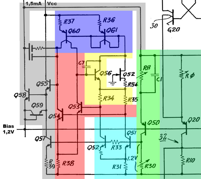
The bandgap reference is based on the well-known principle described in more detail with the AD1403 (https://www.richis-lab.de/REF16.htm). At first sight, however, the circuit is a bit confusing. The core is formed by the transistors Q51/Q52 (cyan). Depending on the currents in the two paths, the transistors Q53/Q54 are driven differently (red). The two transistors are supplied via the current mirror Q60/Q61 (blue), which uses the sum current of the bandgap cell as reference current.

Via the gray path, the potential of the reference current source (light green) is adjusted so that 1,2V is applied to the base of the bandgap reference. If their emitter resistors are set correctly, this voltage is very temperature stable. The following current sources of the DAC (dark green) operate with the potentials of the reference current source.

Capacitance C1 ensures stable operation, as do the capacitors in the gray output stage. Q55 represents a driver, which works with the current sink Q57, which is based on the bandgap reference. In the output stage, transistor Q58 operates with a 1,5mA current source.

The current through the bandgap cell is controlled by Q56 (yellow). The JFET Q52 ensures a clean start-up.


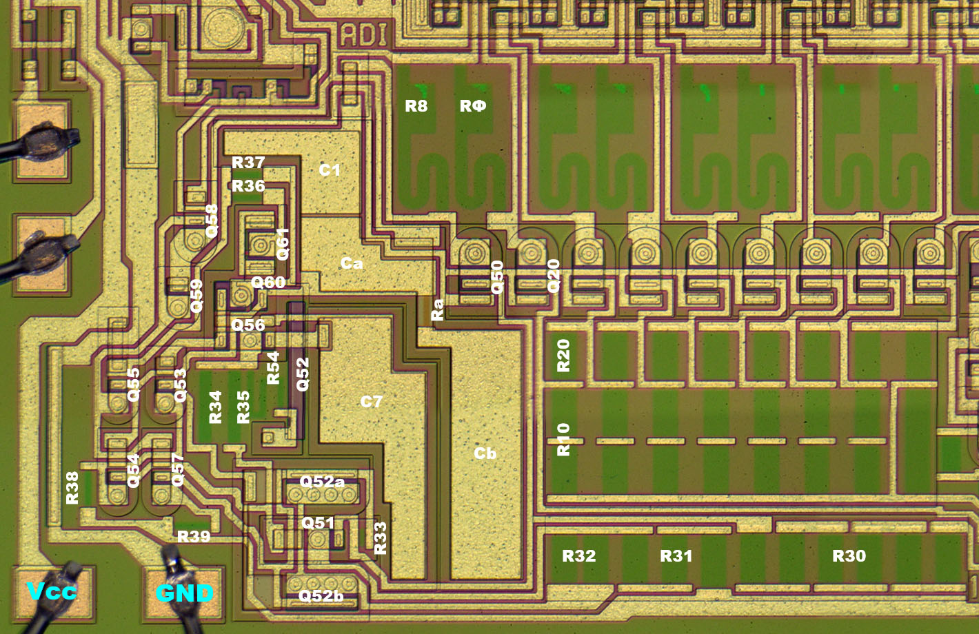
With the reference particularly noticeable are the large capacitors that provide the necessary stability.


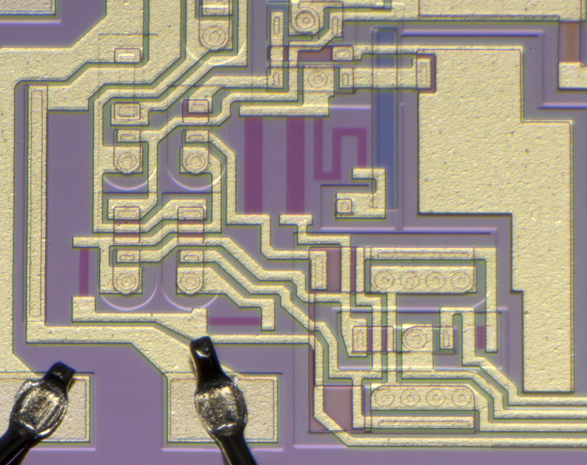
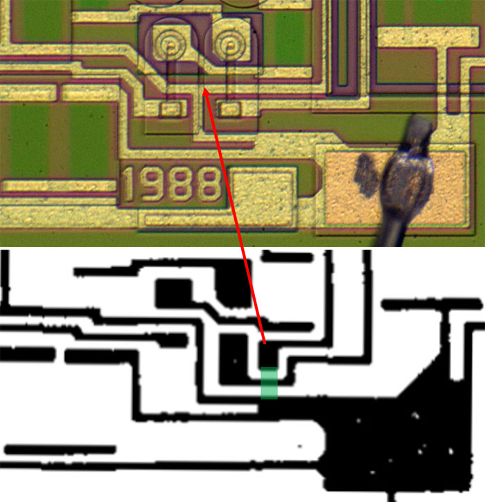
The core of the bandgap reference shows the typical structure. On the bottom right, a small transistor is surrounded by a large, two-part transistor. This ensures that both transistors behave as similarly as possible.


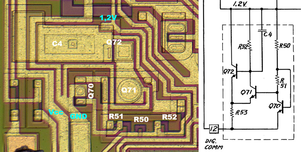
In the shunt regulator for the 1,2V bias, it is noticeable that resistor R53 is missing. R53 is also not visible in the metal layer of the first revision.

The transistor Q72 and the capacitor C4 are integrated into each other.


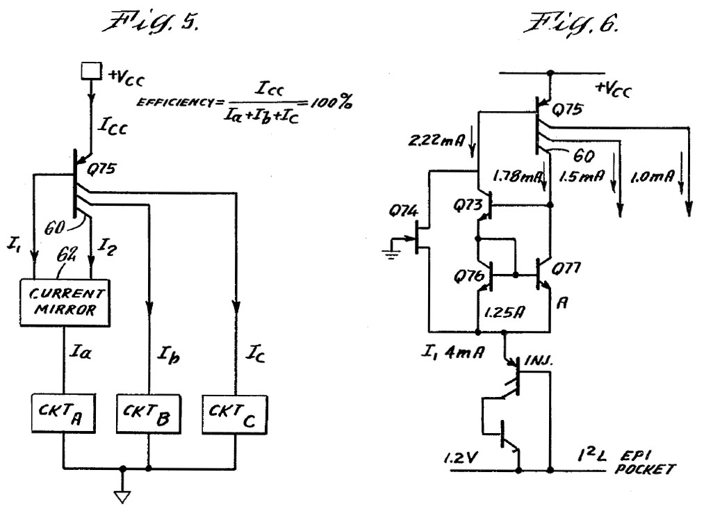
The patent US4323795 emphasizes the efficient generation of the necessary, relatively high working currents. The geometries of the current mirror Q75 and the current mirror Q73Q76/Q77 have been matched so that a constant current is established (Ia). This current can be used directly as a bias current and there is no need for the classic reference path, whose current flow is lost for the actual circuit.

The current source thus supplies the I2L circuit with 4mA, the control output of the bandgap reference with 1,5mA and the control circuit of the I2L buffer with 1mA.


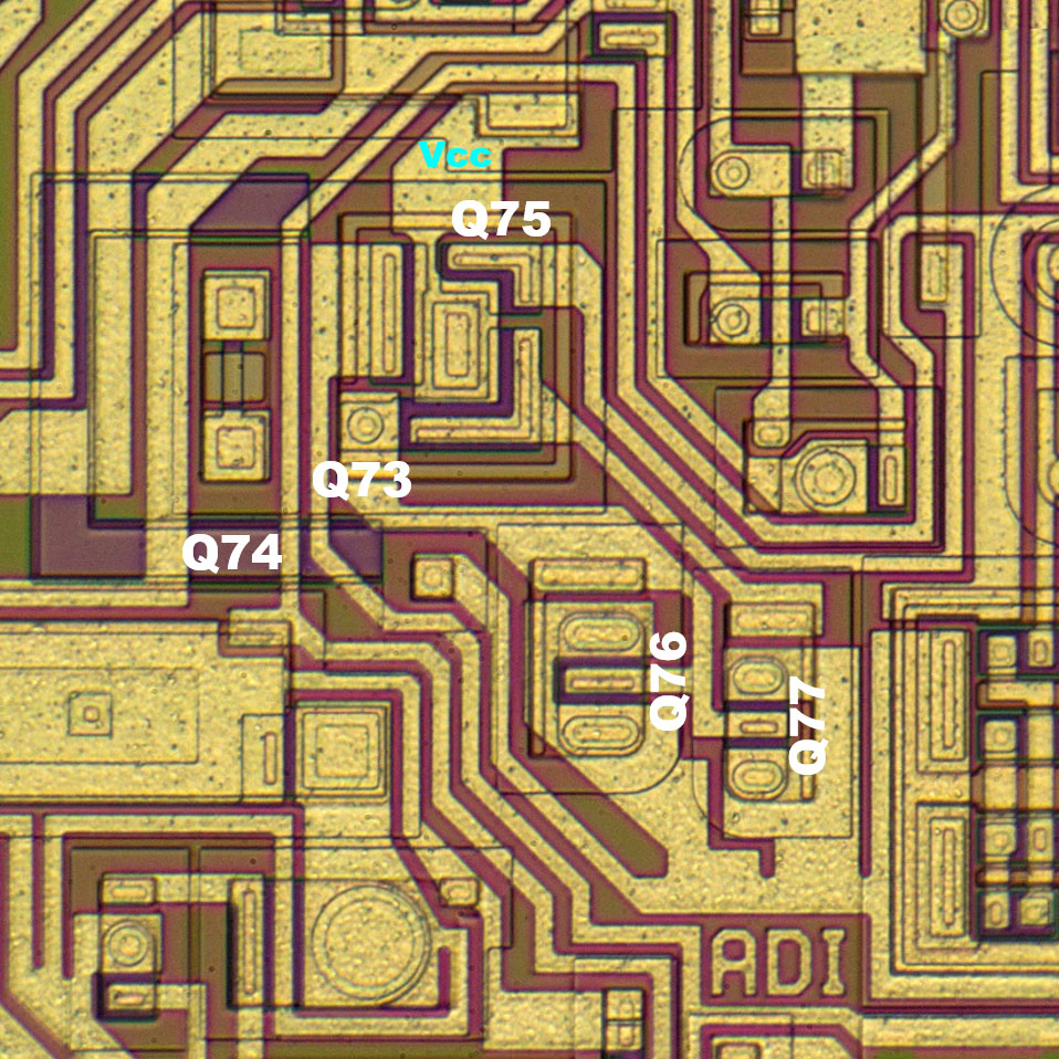
The implementation of the current sources on the die features some interesting structures. Three large collector structures are integrated around the PNP transistor Q75. Due to the close electrical connection, the NPN transistor Q73 is located directly inside these structures. In the lower area, you can see the differently sized transistors Q76/Q77, which supply the I2L area following to the right.


A small circuit links the control signals CS and CE and thus controls the transfer of the applied digital value into the lath.

The transistors with the half emitter arrows are constructed as Integrated Injection Logic (I2L), as described in more detail in the context of the CA3161 (https://www.richis-lab.de/logic22.htm).


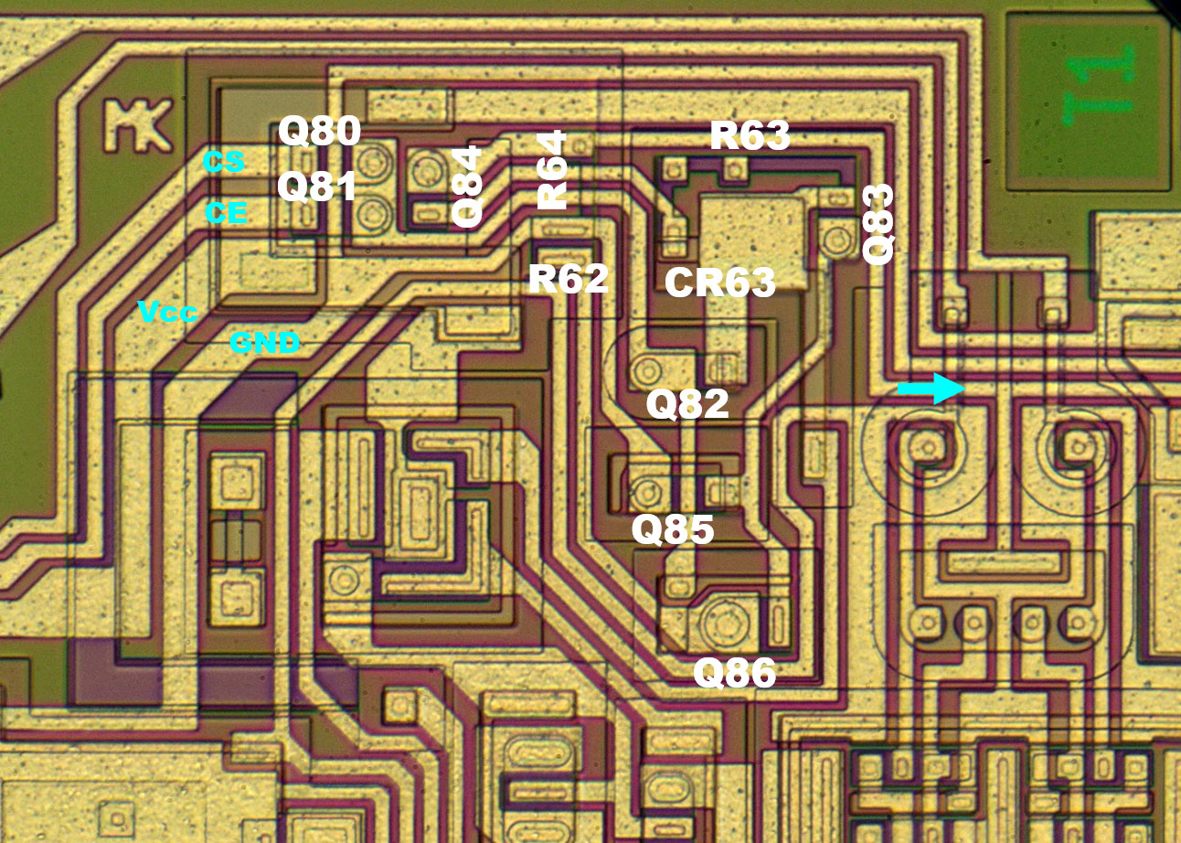
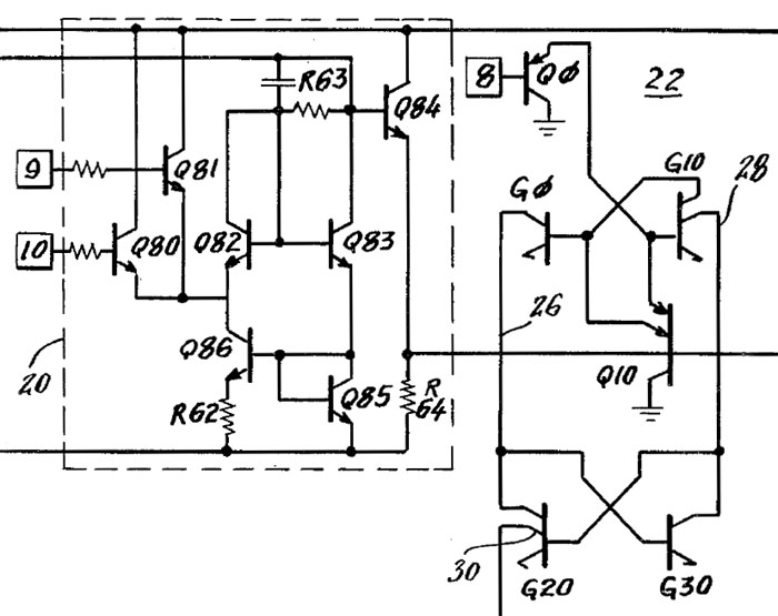
The control circuit of the buffer is integrated in the upper left corner. The resistor R63 has two additional contacts and can thus be adjusted by changing the metal layer. This changes the switching threshold of the inputs.


The use of I2L technology made it possible to integrate the latch in a very space-saving manner. The injection current is fed into the area from the current source on the left and contacts the individual I2L elements with quite low resistance.


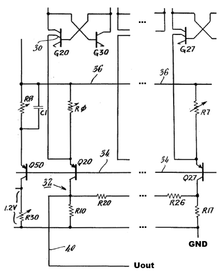
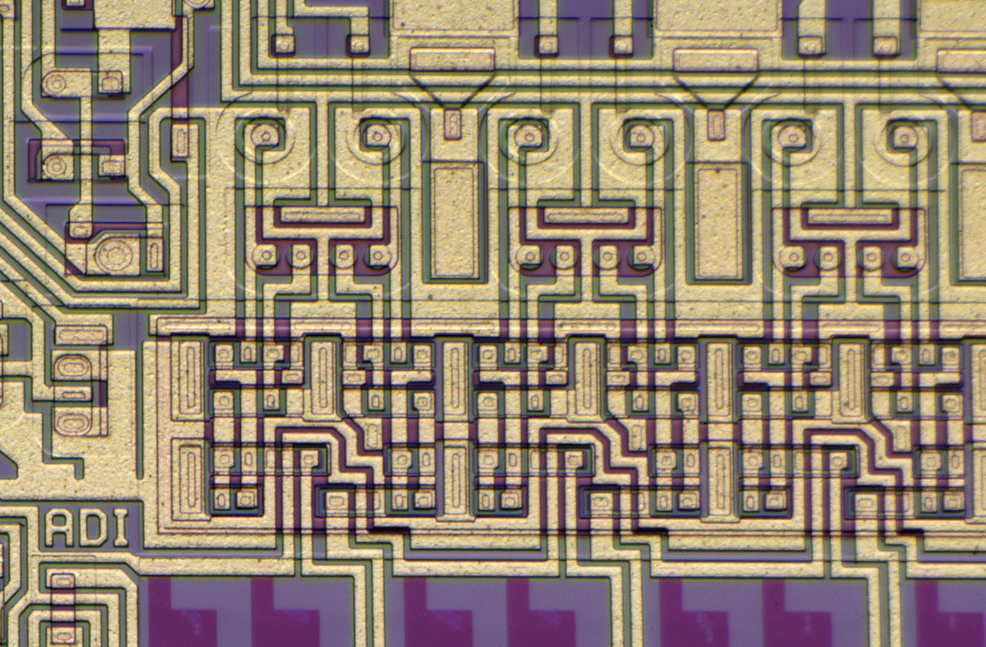
The actual DAC is shown in abbreviated form in the patent circuit. The emitter resistors of the current sources are adjustable to be able to represent a high accuracy. Below the current sources is the R2R divider, which ensures that the current sources further to the right only contribute a portion according to their weighting. The output voltage adjusts between 0V and 400mV.


The reference current source (Q50) is integrated directly next to the eight current sources of the DAC and has exactly the same shape. This measure ensures that all current sources behave as identically as possible.

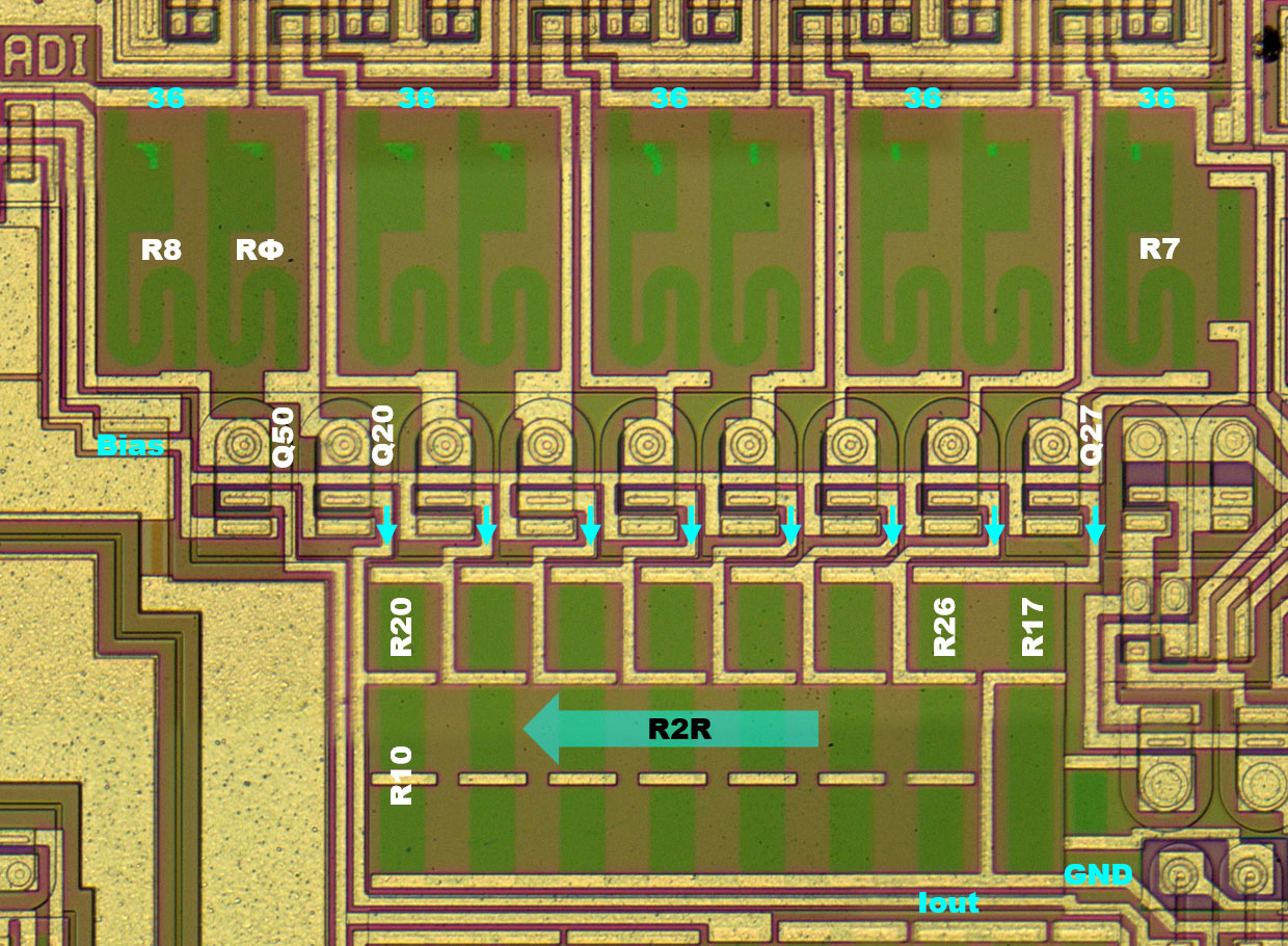
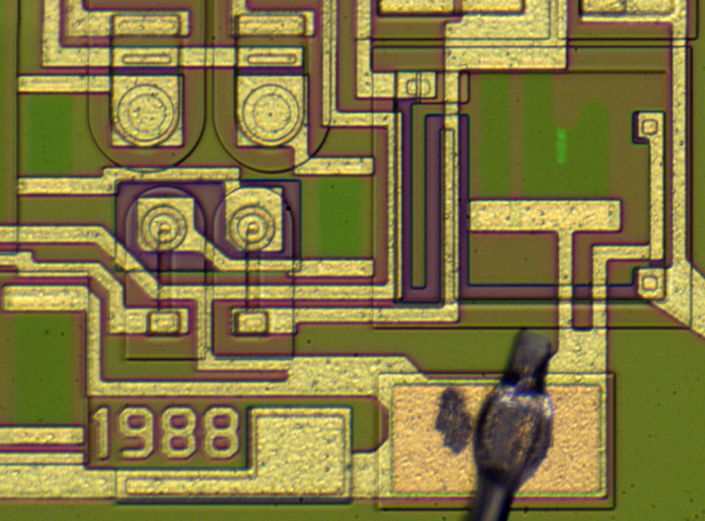
The emitter resistors are clearly visible. Every resistor was tuned. However, the right elements show less alignment traces. The accuracy requirements are lower because of the smaller contribution of the current sources and probably less effort was put into the tuning.

At the top edge, the emitter potential "36" is distributed. In the middle, the PNP transistors generate the necessary currents whose contributions to the output voltage are scaled in the R2R network. To achieve a high symmetry with the resistors, there is a resistor strip under R17, although it is not needed in the circuit.


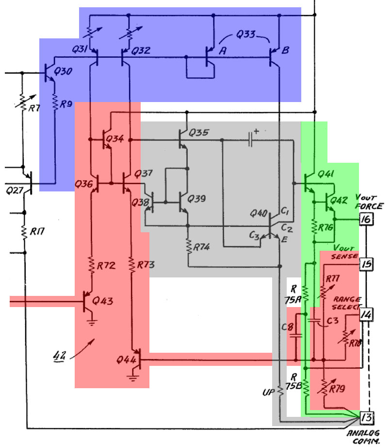
The output amplifier uses the potentials of the DAC current sources to generate its bias currents (blue). The input stage (red) has an unusual design. PNP transistors Q43/Q44 process the output signal of the DAC and the feedback that is fed back from the output. They are located in the emitter paths of current mirror Q34/Q36/Q37.

At the collector of transistor Q37 the signal is passed to the next amplifier stage (gray), which controls the output driver Q41 (green). With R76 Q42 represents an overcurrent protection. Depending on the external connection of the resistors R77/R78/R79, an output voltage range of 0-2,56V or 0V-10V can be set. If the external wiring is missing, the resistors R75A/R75B form a certain negative feedback.

The gray circuit contains a very unusual element with the transistor Q40. The illustration shows a transistor with two emitter terminals and two collector terminals, with one emitter terminal designated C3. The patent US4323795 explains that this particular transistor was integrated to compensate for a fundamental problem that arises when one wants to operate DACs without a negative supply. When the output signal approaches ground potential, the driver stage tends to saturate, which severely degrades the dynamic range of the amplifier.

The additional emitter C3 improves the saturation behavior. In normal operation, no current flows across it. However, if Q40 goes into saturation, the potential at C3 drops below the base potential of Q35. In this state, the additional emitter behaves like a collector and sinks base current from Q35. This results in Q40 being driven less and leaving saturation. The additional collector C2 just provides a Kelvin connection to the collector C1, which reduces the voltage drop in the path of the output stage.


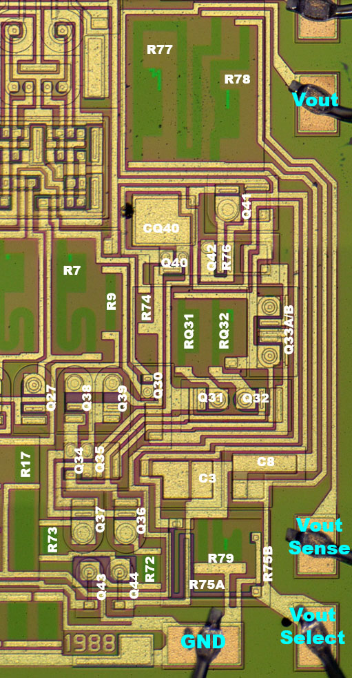
In the output amplifier, the adjusted resistors for the current sources and the voltage divider of the output voltage are clearly visible.


Without the description in the patent it would be difficult to recognize the function of the transistor Q40.


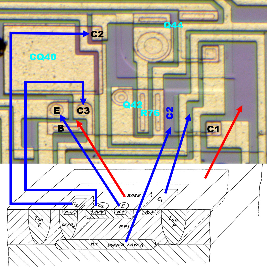
The patent shows a sectional view of this special transistor. C1 and C2 represent a normal collector, with C2 being more low-impedance connected to the active area via a buried, highly doped layer. C3 is a heavily n-doped region within the base area and thus represents an emitter rather than a collector.

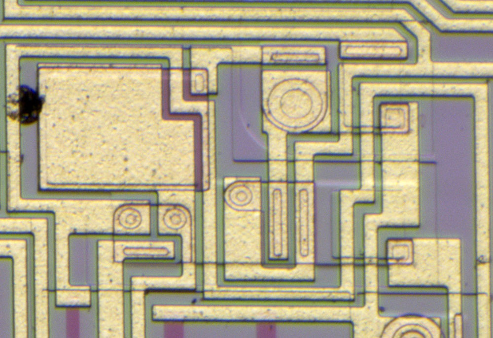
In the real structure, the two emitters have the same structure. On the far right, the collector C1 is contacted. The nearly square area then is the surface n+ doping. In the middle of the structure Q42, the current limiting transistor of the output stage, is integrated. Since its collector potential is the C2 potential, it directly uses the collector area of transistor Q40. Shunt R76 has been integrated here too.

The buried collector extends over the whole area of the two transistors and further to the upper left, where it widens and represents the lower electrode of the capacitor CQ40. Finally, the connection from the collector C2 to the output transistor Q44 is located there.


The two PNP input transistors of the output amplifier show an interesting structure. Since the n-doped base is formed via the collector structures of the NPN transistors, a buried collector feed line could be used here in order to be able to represent the undercrossing of a metal line with low impedance. This collector (now base) feed line shows up here as a thin line within the weak n-doped elongated rectangle.


In the schematic in the patent the transistor Q40 is connected to the emitter resistor Rup. On the die this resistor doesn´t exist. The metal layer of the older revision shows that in this version the resistor was probably still present (green).


https://www.richis-lab.de/DAC24.htm

 :-/O
 
The following users thanked this post: D Straney

Offline NoopyTopic starter

  • Super Contributor
  • ***
  • Posts: 1816
  • Country: de
    • Richis-Lab
Re: DACs - die pictures
« Reply #111 on: September 07, 2023, 10:03:36 am »


The HA16633 is a DAC with a resolution of 16Bit developed by Hitachi. Unfortunately, very little information is available about this device.


The HA16330 was used by Hitachi in their DA-1000 CD player. The above advertisement for the DA-1000 is from the magazine Audio, February 1983 (issue 2). It shows the special circuits developed by Hitachi, including the HA16633. However, the DA-1000 was quickly switched to Burr-Brown's PCM53 DAC. The service manual from March 1983 you can find the HA16633, the April 1983 version already refers to the PCM53. The version with the PCM53 was called DA-1000R by Hitachi. It is marked with an R on the back of the case.

The DA-1000 was sold under other names by various other manufacturers: Brandt DAD-001, Continental Edison DAD-9370, Denon DCD-2000, Dual CD 120, JVC XL-V1, Nordmende ADS-2000, Pathe Marconi LA-10, Saba CDP 380, Thomson AD-100.


In the IEEE article "An Untrimmed D/A Converter with 14-Bit Resolution" Hitachi employees describe some details about the operation of the HA16633. The 14-bit DAC presented there was the basis for the HA16633. One was already confident to be able to extend the concept to 16Bit.

As a DAC for a CD player, the HA16330 had to offer a sufficiently high resolution and at the same time be as cheap as possible. In order to be able to do without a time-consuming laser adjustment of the integrated resistors, one integrated a circuit, which makes it possible to determine errors of the DAC. The necessary correction values are stored in a memory and control additional circuits in the area of the DAC during further operation, which correct the error of the output voltage.

The principle of operation is similar to that which would have been planned for the C5360, which is described in the context of the TF536 (https://www.richis-lab.de/DAC09.htm). The errors are determined by comparing the output voltage with a voltage ramp. By this procedure one does not have to determine a voltage exactly, but just a time period, which is a lot easier.


The voltage ramp is generated with an external capacitor. A comparator compares the voltage ramp with the current output voltage of the DAC.

Counter 2 serves the 5 MSBs of the DAC, where the absolute errors of the individual bits have the greatest effect. The counter ensures that all 32 states of these five MSBs are selected in sequence. For each value a correction value is determined.

To develop the correction value, counter 1 counts the pulses of the clock signal that is supplied from outside. If the voltage ramp reaches the potential of the output voltage, the counter stops. The determined value is stored and counter 2 is incremented to adjust the next stage. If the circuit and the clock frequency are designed correctly, then the counter directly generates the necessary correction value, which can easily be stored in the memory.

The "Selector" provides access to the input of the DAC. In normal operation, the five MSBs control not only the DAC, but also the selection of the necessary correction value in memory.


Depending on when the comparator switches, either more or fewer pulses are counted. The number of pulses is proportional to the error of the steps. With a clock signal of 1MHz the 14Bit concept DAC needs 120ms for one run of the ramp.


The voltage ramp of the HA16633 must be sufficiently linear. Critical is the integration capacitor, which must be conncted externally. The most suitable are styrene capacitors whose linearity is sufficient to represent an adjustment of up to 17Bit.


There are two very similar IEEE articles describing the concept of the HA16633. Both documents are titled "An Untrimmed D/A Converter with 14-Bit Resolution". One document was presented at the 1981 IEEE International Solid-State Circuits Conference. The second document can be found in the IEEE Journal of Solid-State Circuits, Vol. SC-16, No. 6. The first document describes just a single alignment. The second document describes a somewhat more complex procedure and also contains a diagram showing the residual errors.

As already shown, the clock signal and the voltage ramp must be adjusted in such a way that the necessary correction value results directly from the state of counter 1. Since it is difficult to reach this operating point exactly, an adjustment takes place within the control logic. If a relevant deviation is detected at the maximum value of the counter during the first adjustment, then the control circuit modifies the number in counter 1 at each stage of the digital-to-analog converter. According to the IEEE article, the adjustment is performed a total of three times.


The service manual of the DA-1000 contains a complete circuit diagram of the CD player, a block diagram of the HA16633 and an adjustment instructions. According to this, in addition to an analog and a digital reference potential, the device is supplied with four other potentials: 12V, 8V, 5V and -5V. In the block diagram pin 31 is marked with the letters INT. In fact, however, it must be called INJ, since the pin supplies the I2L logic of the device ("injector"). The reference voltage is generated internally, output via pin REF OUT and is taken back via pin REF IN. At pin CEX you can apparently connect a capacitor for noise suppression. Most likely, the capacitance de-noises the reference voltage source.

The concept of the error corrector corresponds to a large extent to the concept from the IEEE articles. Pin IVOL can apparently be used to set the slope of the voltage ramp used for adjustment. The integration capacitor is to be connected to the pins INT IN and INT OUT.

Here, too, just the 5 MSBs are corrected. A 6Bit counter activates the individual stages of these 5 Bits one after the other and then disables the clock signal. The second counter that determines the correction values is a 12Bit counter. The RAM takes over the correction values of the 12 Bit counter, but just 8 Bit of it. This fits to the representation in the IEEE articles. But it will be shown that the RAM has just memory cells for 256 Bit and so not more than 8 Bit correction values for the 32 stages can be stored. In normal operation, the RAM is addressed with the five most significant bits that are present at the digital interface. The memory then automatically transfers the appropriate correction values to the DAC.

The function of the so-called "4bit link" remains unclear. There is no explanation in the IEEE articles. The arrow leads to the block "amplifier correction circuit for downstream 11 bits". Its function is equally unclear. The correction circuit for the errors of the DAC is integrated in the DAC block. For this reason, the correction data of the RAM is also routed directly there. Maybe the path "4bit jack" is an error in the block diagram or an inaccurate representation of a function of the control logic. As described earlier there is a correction of the maximum value of the counter.

The pins RO1 to RO8 are not found in the block diagram. In the listing of the connections the interface is described as "connection for RAM test". Apparently one has created an interface to the internal RAM here. This is surprising, since after all there are eight pins that were reserved for this purpose. During production, no detailed measurement of the component was necessary, since no alignment took place. Perhaps this is why the possibility was created to check the initial errors of the DAC and thus the quality of the integrated circuit via this RAM interface after production.


The adjustment instructions of the DA-1000 describe a step that is to be performed on the HA16633. This involves using resistor R403 to adjust the voltage ramp of the DAC to the clock signal. The automatic self-tuning of the HA16633 is apparently triggered every time the door of the CD drive is closed. As a result, a frequency counter at the COUNT pin (TP.6) can be used to count the pulses that control the 12 Bit counter during the adjustment. The target value according to the service manual is 254.000 +/-1.000. A diagram shows that from a deviation of +/-6.000 the distortions increase strongly.

The 254.000 pulses fit the overall picture well. With this number of pulses, the 12 Bit counter can be filled 62 times. The five MSBs of the DAC actively represent 31 stages. This means that the complete calibration is done twice.


[...]

 :-/O
 
The following users thanked this post: oPossum, MegaVolt

Offline NoopyTopic starter

  • Super Contributor
  • ***
  • Posts: 1816
  • Country: de
    • Richis-Lab
Re: DACs - die pictures
« Reply #112 on: September 07, 2023, 10:04:41 am »


If the epoxy is decomposed at high temperatures, the die with dimensions of 5,7mm x 4,8mm can be exposed. A dark layer remains on the surface. This is usually a polyimide layer that protects the circuit and can also be burned and removed at elevated temperatures. Here, however, it is noticeable that lines are surprisingly clearly visible in the dark layer.


The already mentioned IEEE article refers to another IEEE article with the title "Planar Multilevel Interconnection Technology Employing a Polyimide". It describes a special way to apply a second metal layer to an integrated circuit. The unusual feature is that there is a polyimide layer between the metal layers. Another polyimide layer is used as a passivation layer. This technique seems to have been used for the HA16633.


The IEEE article goes on to describe that it is a special polyimide that can withstand even slightly higher temperatures: "polyimide isoindroquinazoline-dione" or PIQ. The temperature resistance is necessary so that the second aluminum layer can be applied to the first polyimide layer.


These more temperature-resistant polymide layers can also be decomposed at elevated temperatures. Unfortunately, the second metal layer is also lost in the process.


This HA16633 was chemically opened at HTV (https://www.htv-gmbh.de/). If this process is mastered, it is even possible to preserve the bondwires, as can be seen here.


The bondwires are completely undamaged chemically and mechanically.


At the edges of the opening the filler contained in the epoxy can be seen. These are very different silicon oxide fragments with a diameter of up to 100µm. For modern components the filler is often specified much more precisely. In some cases even silane is burned to produce silicon oxide with exactly the desired properties.


The chemicals used to dissolve the epoxy have unfortunately dissolved the polyimide too. The second metal layer is partially still present relatively undamaged, but in some cases it has been completely lost. In some places, even the first metal layer has been attacked. As soon as the protective polyimide layer is dissolved, the first metal layer is completely exposed to the acids. In other components that use silicon oxide or silicon nitride as a passivation layer, the metal layer remains protected by the passivation layer apart from the bondpads.


The lines of the second metal layer have set up in some places and partially obstruct the view of the circuit parts below.


[...]

 :-/O
 
The following users thanked this post: Miyuki, D Straney

Offline NoopyTopic starter

  • Super Contributor
  • ***
  • Posts: 1816
  • Country: de
    • Richis-Lab
Re: DACs - die pictures
« Reply #113 on: September 07, 2023, 10:05:45 am »


On the edge of the dies is the designation HA16633.


There are also squares that are most likely used to check the alignment of the masks against each other.


Only one functional test structure is integrated on the die. It is not a simple transistor, but an I2L element. The functionality of an I2L, "Integrated Injection Logic", is described in more detail in the context of the CA3161 (https://www.richis-lab.de/logic22.htm).


Four bipolar transistors are also found in the edge area of the die. However, these structures do not have any contacts.


In the IEEE articles there is a picture of the 14Bit DAC concept. This die is 5,2mm x 4,1mm, contains 1230 I2L gates and 470 so-called linear components.

The individual functional blocks are labeled and in some cases clearly separated from each other. This makes sense, so that the circuit parts do not interfere with each other, but it is also partly due to the different technologies used for control logic, memory cells and the analog peripherals.

Between the functional blocks there is a large number of testpads. The authors of the IEEE articles assume that the silicon area could be reduced by 72% and a package with 28 pins would be sufficient.


The arrangement of the circuit parts is very similar in the HA16633. The signal routing is difficult to analyze due to the damaged metal layer, but you can see some larger bus systems.

The lines of the potentials RO1-RO8 have unfortunately suffered a lot on all pictures. However, they seem to have led to the left to the output of the RAM. This speaks for the theory that the content of the memory could be read with these pins.


The I2L control logic in the right part of the die is located in a light green tub, which clearly distinguishes it from other circuits. Smaller logic areas are also found below the analog section and next to the RAM block.

The control logic consists of several rows where the I2L gates are lined up next to each other. Several thick resistor strips are integrated in the center, representing series resistors in the I2L supply.


The I2L structures can be clearly seen. The mode of operation is described in more detail in the context of the CA3161 (https://www.richis-lab.de/logic22.htm).


The memory area is also clearly visible due to its regular structure. It is surrounded by circuit parts that allow cells to be selected, read out or written.


It is relatively easy to understand that each pair of purple stripes represents a memory cell. However, the functionality is not immediately obvious.


An explanation is provided by the magazine Electronics (February 14, 1972). The six transistors that make up the structures and their interconnection are difficult to see because parts of the silicon are used by several elements. This is at the same time a challenge of this memory technology. One has to adjust the layer thicknesses and dopants in such a way that no uncontrolled conductivity occurs as in a SCR. The individual cells behave like a flip-flop.


In the analog circuit parts in the lower area, the DAC is relatively easy to identify. The other elements like comparator, reference voltage source and integrator are more difficult to identify, mainly because the second metal layer is missing.

Since no adjustment was done during manufacturing, one probably had to accept some weaknesses in the initial accuracy and the temperature drift of the reference voltage. Both parameters are usually calibrated. The IEEE articles specify a temperature drift of 20ppm/°C.


The IEEE articles show how the main DAC is linked to the correction DAC. The 11 MSBs of the DAC (D14-D4) switch 11 equal current sources that are tied to an R2R resistor chain to provide matching contributions to the output level. The 3 LSBs (D3-D1) control 3 transistors connected to a common current sink. The different sizes of the transistors result in suitably stepped current contributions. Above the transistors only simple switches are shown. In fact, they are toggle switches so that the respective current shares do not change. For the same reason, the second 4x transistor is necessary, which is permanently connected to the supply voltage. This is the only way to achieve the necessary ratio of 16:8:4.

The correction DAC offers a resolution of 8 Bit. The 3 MSBs (C6-C4) switch further current sinks and connect them directly to the R2R divider of the main DAC. This saves the integration of another resistor chain. In addition, there is a current sink with five transistors of different sizes above it (C3-C1/4). Here the ratio is 16:8:4:2:1.

The IEEE articles state that the largest errors are generated by the 5 MSBs. Usually the errors are not larger than +/-32LSB (related to 14 Bit). The above design theoretically allows for alignment down to +/-1/4LSB. Practically, the IEEE articles specify +/-1/2LSB, but show results just in the range of +/-1LSB.


The circuit parts of the DACs can be easily identified on the HA16633. In the lower area there are 17 resistors, each of which is represented by a series connection of three slanted resistors (light green). Above them are 14 switchable current sinks and 3 non-switchable current sinks (dark green). Above the current sinks, the R2R current divider is made up of slanted, longer resistor strips (yellow). At the current sinks you can see that bits D8-D6 are connected to correction current sinks (C8-C6).

Above the R2R current divider are the transistors of different sizes, with two current sinks representing the remaining portions of the main DAC (D5-D1) and the correction DAC (C5-C1). The equal size ratios of the main DAC and correction DAC are clearly visible. Above them are the associated toggle switches.

There remains a current sink exclusively connected to a transistor of size "4x" (I_R0). The purpose of this path remains open. The base of transistor I_R0 is connected to the emitters of the transistors C5-C1. An influence in this direction should not take place. It´s not possible to reconstruct to what the collector of the transistor was connected. Maybe a control loop closes here, which sets the operating point of the DAC.


If the IEEE schematic is modified accordingly, it shows that for the extension of the main DAC to 16 Bit, the transistors above the last current sink were just supplemented by two additional, correspondingly smaller transistors. The correction DAC has not changed, whereby now the lowest bits there only reach C1, thus allowing at most a correction by +/-1LSB. With the specifications of the IEEE DAC, one can assume that the HA16633 can adjust to +/-2LSB at most, probably even only to +/-4LSB.


The remaining analog circuit parts are much more difficult to identify.


The circuit of the comparator is shown in the IEEE articles. It should have a response time of 130ns or less.


https://www.richis-lab.de/DAC25.htm

 :-/O
 
The following users thanked this post: ch_scr, D Straney


Share me

Digg  Facebook  SlashDot  Delicious  Technorati  Twitter  Google  Yahoo
Smf