Author Topic: Automotive ignition secondary scope circuit design  (Read 4207 times)

0 Members and 3 Guests are viewing this topic.

Offline torchTopic starter

  • Frequent Contributor
  • **
  • Posts: 397
Automotive ignition secondary scope circuit design
« on: May 02, 2011, 12:09:36 am »
I picked up this set of leads to monitor ignition output on a scope:
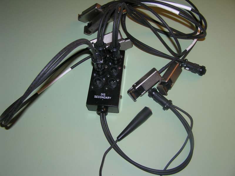
.
The idea is that one can display a chain of ignition pulses. Variations in amplitude can help identify misfires etc. Unfortunately, it turns out these are designed to work with a particular specialty scope, don't have BNC connectors, etc. So I'd like to adapt it.

The big black box is nothing more than a j-box. Here's the schematic:
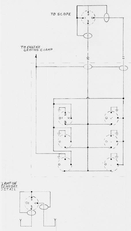
The pickups are nothing more than a piece of copper soldered to the co-ax conductor -- basically, an antenna. Those are ganged together into two outputs. Here's the problems I identified:
There's no way to identify which cylinder is displayed and it requires both channels to display all cylinders. (I want them all on one so the other channel is available to monitor another system at the same time)
Waste spark systems show an inverted waveform on half the cylinders.
If there is a flaw or failure of the ignition wire insulation, the scope inputs will be subjected to tens of KV -- more than most scopes can handle!

I've been playing around with some ideas, and come up with the following modifications:
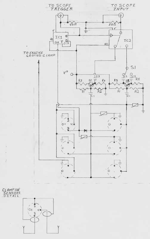
However, I don't really know what I'm doing, and would appreciate some help with this -- a better design, or help figuring values for "my" design (cobbled together from some circuit fragments I found on the net.)

Here's what I'm trying to accomplish: First of all, MOVs for the inputs in case of insulation failure.
Second, a diode on one input to separate out a trigger source.
Next, Q2 is a phase splitter with one output 180° from the input. The two outputs feed S1, to correct the waveform for waste spark systems. Q1 is just there to ensure the other bank is processed equally.
IC1 is a toggle flip-flop to divide the trigger pulses by two. This in turn toggles IC2 to alternate banks so the waste spark will be ignored. That is, only pulses from bank 1 will be passed to the output (ignoring waste spark from bank 2) then when the waste trigger occurs it is suppressed and IC2 feeds bank 2 to the output (suppressing waste spark from bank 1).

Well, that's the theory anyway. My projects always work well in theory...

Measured raw voltage, using 10x probes connected to the connector pins, ranged from 15v to 120v peak-to-peak. For powering these mods, I think I'd either like to use a 9v battery or a couple of alligator clips right off the vehicle's battery.

If it's not completely obvious yet, I don't know what I'm doing. HELP!!! Please.


Offline Kiriakos-GR

  • Super Contributor
  • ***
  • !
  • Posts: 3525
  • Country: gr
  • User is banned.
    • Honda AX-1 rebuild
Re: Automotive ignition secondary scope circuit design
« Reply #1 on: May 02, 2011, 12:28:37 am »
Well, this is the probes of an professional ignition analyzer. 4-6 cylinders .

An system that costs thousands of dollars, but as complete unit , hardware and software.

Usually the hardware comes as complete device,  with special software, and the software are made by major brands of the car industry.
( most of them )
You are trying to simplify things, so to work with a common scope ?
That's a true long shot my friend, I do not think that it will work , no matter how hard you will try.   


Offline torchTopic starter

  • Frequent Contributor
  • **
  • Posts: 397
Re: Automotive ignition secondary scope circuit design
« Reply #2 on: May 02, 2011, 01:06:42 am »
Well, this is the probes of an professional ignition analyzer. 4-6 cylinders .

Up to 12 actually. But I only have leads for 8 -- which is fine, my car only has 8 cylinders anyway.

Quote
An system that costs thousands of dollars, but as complete unit , hardware and software.

Usually the hardware comes as complete device,  with special software, and the software are made by major brands of the car industry.
Yup. This one was made for Ford. Actually, for this application there is no software required -- it's all hardware and wetware. But I know what you mean -- I have 3 different scan tools for interfacing with various ECU and CAN bus systems. Let's just say they cost more than I care to admit to my wife ;). There is an aftermarket device (Pico Mixmaster) that does exactly this -- for around $400, all in.

Quote
You are trying to simplify things, so to work with a common scope ?

Yes.

Quote
That's a true long shot my friend, I do not think that it will work , no matter how hard you will try.   
Fools rush in where angels fear to tread.  :D
 

Offline Kiriakos-GR

  • Super Contributor
  • ***
  • !
  • Posts: 3525
  • Country: gr
  • User is banned.
    • Honda AX-1 rebuild
Re: Automotive ignition secondary scope circuit design
« Reply #3 on: May 02, 2011, 03:58:39 am »
Ok , I will change my song ...  

I wish you good luck and plenty of it ..  ;D
 

Offline insurgent

  • Regular Contributor
  • *
  • Posts: 78
Re: Automotive ignition secondary scope circuit design
« Reply #4 on: May 02, 2011, 05:05:33 am »
Quote
Let's just say they cost more than I care to admit to my wife ;).

I hear you, my friend. Fortunately my wife is into the home renovations like apparently Dave's wife is. So anytime the price becomes an issue for one of my $300 , I just cough and politely mention the prices for the new couch, new hardwood floor, the new stucco on the house, the new addition, the new rood, etc ;)
 

Offline Mechatrommer

  • Super Contributor
  • ***
  • Posts: 11700
  • Country: my
  • reassessing directives...
Re: Automotive ignition secondary scope circuit design
« Reply #5 on: May 02, 2011, 09:44:44 am »
Quote
Let's just say they cost more than I care to admit to my wife ;).
I hear you, my friend. Fortunately my wife is into the home renovations like apparently Dave's wife is.
count me in to. we are done but i'm still getting back on my feet.
Nature: Evolution and the Illusion of Randomness (Stephen L. Talbott): Its now indisputable that... organisms “expertise” contextualizes its genome, and its nonsense to say that these powers are under the control of the genome being contextualized - Barbara McClintock


Share me

Digg  Facebook  SlashDot  Delicious  Technorati  Twitter  Google  Yahoo
Smf