PART 1You will need some time to read this.

The Analog Devices AD679 is a 14Bit subranging SAR Analog Digital Converter.
There are six different versions: A, B, J, K, S, T. K gives you the best specifications. T can work in an temperature range between -55°C and 155°C.
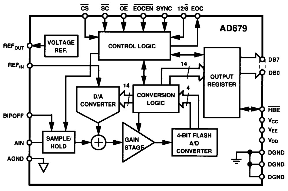
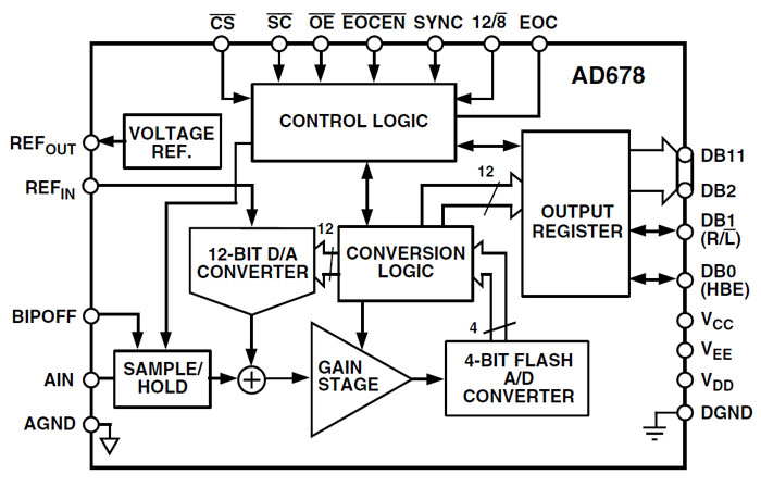
The datasheet shows the architecture of the AD679. In the first place there is a Sample&Hold stage giving you 10M/10pF input impedance. The input signal is fed into a summing node from which a DAC draws current. That´s a normal SAR ADC but instead of a comparator the AD679 uses a 4Bit-Flash-ADC with an amplifier that quantifies the residual signal. With this architecture the AD679 needs just five cycles to get 14Bit while a normal SAR-ADC would need 14 cycles.
(There is a 12/8 pin. In the AD679 pinning you won´t find a 12/8 pin. Furthermore there is no explanation for the 12/8 pin in the datasheet. We will see...)
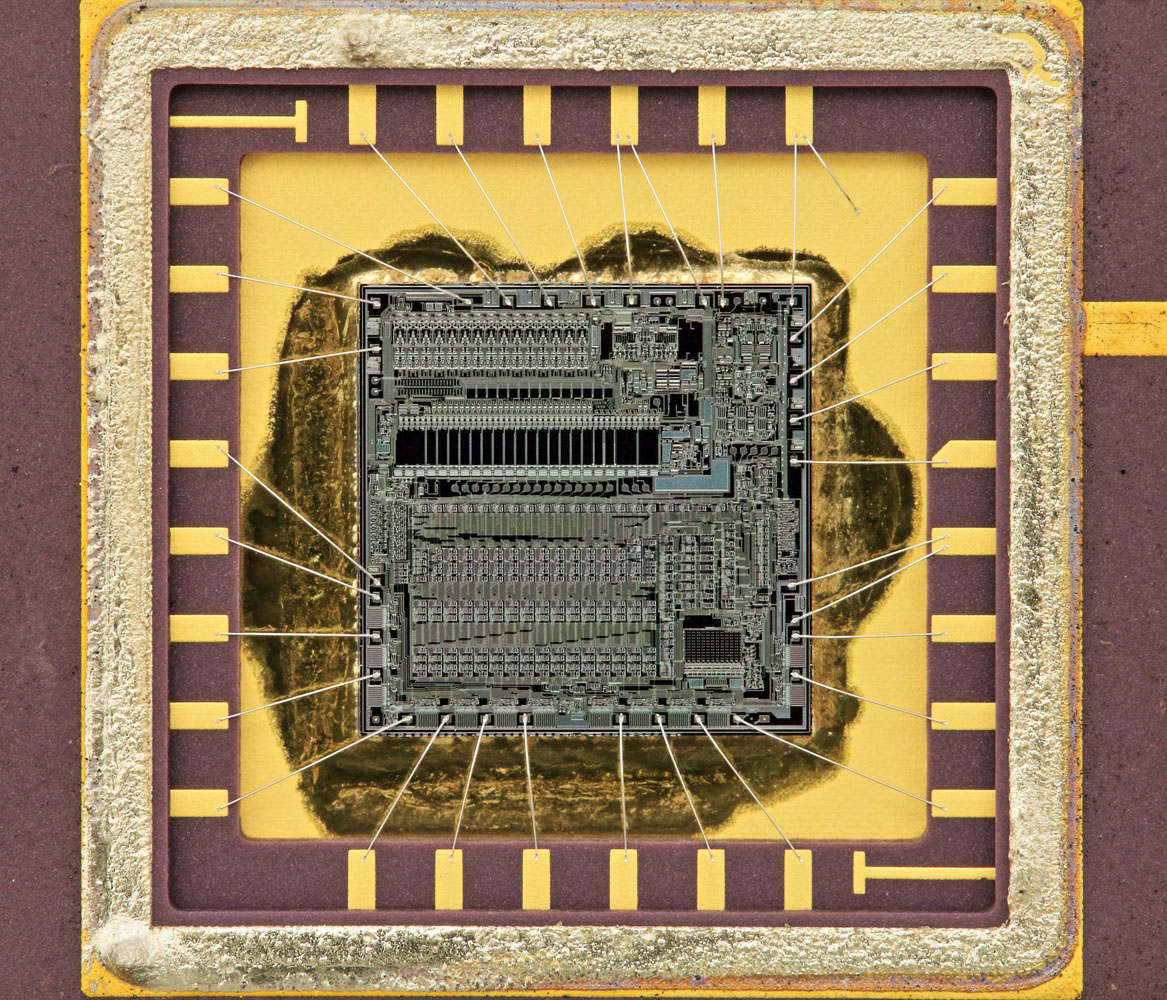
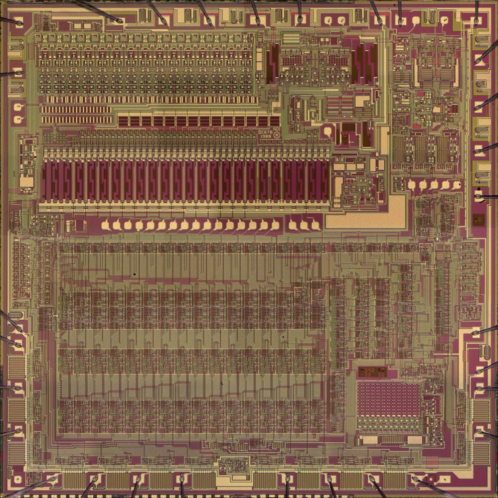
The die is really big (6,5mm edge length).
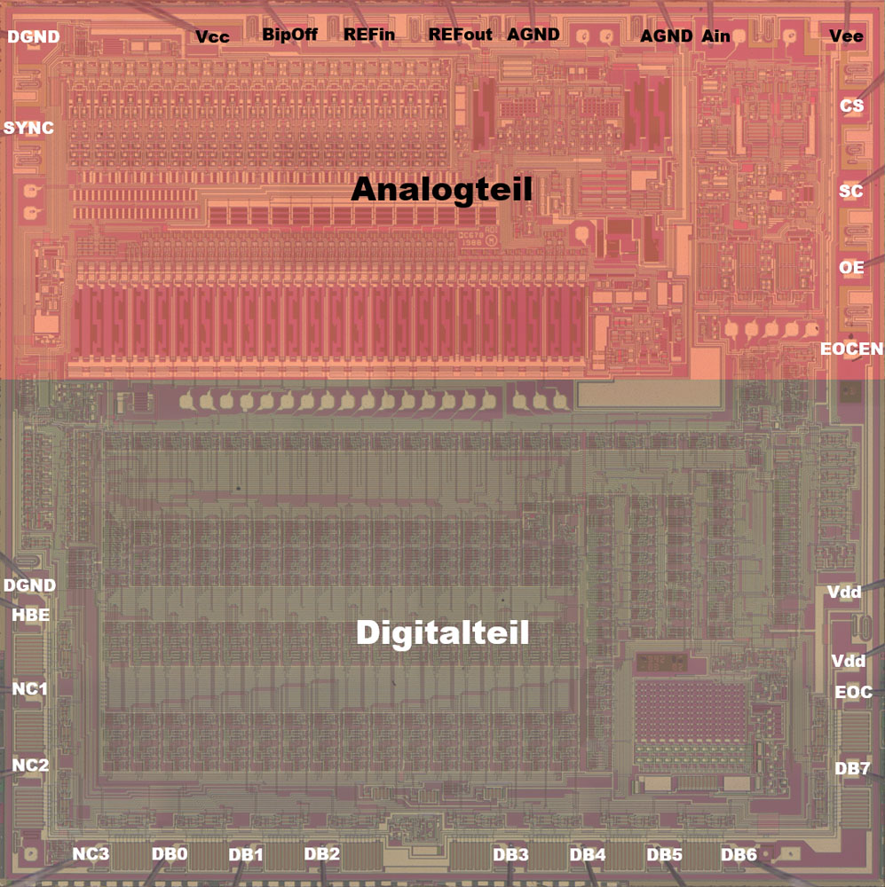
The digital part is a little bigger than the analog part.
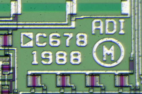
It looks like the AD679 was designed in 1988.
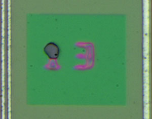
C678? AD678?
The AD678 is nearly the same as the AD679. While the AD679 converts 14Bit with a sample rate of 128kS/s the AD678 gives you 12Bit with a sample rate of 200kS/s.
(Now we know where the 12/8 pin comes from! Analog has copied it from the AD678 datasheet!)
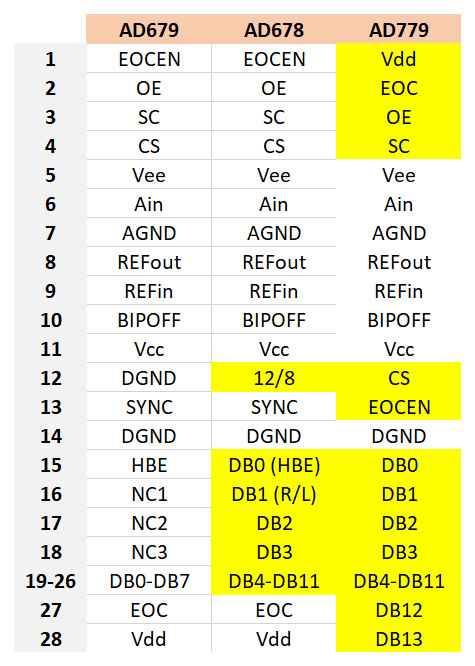
The pinning of the AD678 is quite similar to the AD679. The AD678 gives you the possibility to use a 12Bit interface and you can switch it to 8Bit (with the 12/8 pin). It looks like the AD678 and the AD679 use the same die.
There is also a AD779 with the same specifications as the AD679 but with a 14Bit interface. However the AD779 has to contain a different die because on the AD678 die there are just 13 outputs and you need one for EOC.
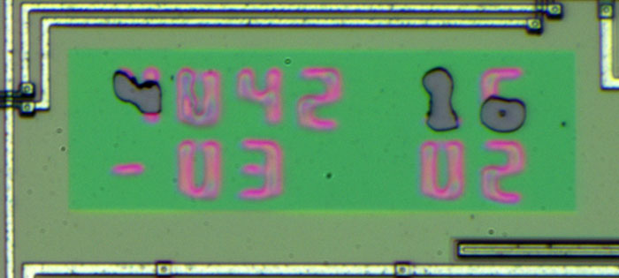
There are some laser tuned resistors on the die. You can find some numbers perhaps for binning perhaps to retrace the tuning process.
It seems like the passivation layer is damaged.
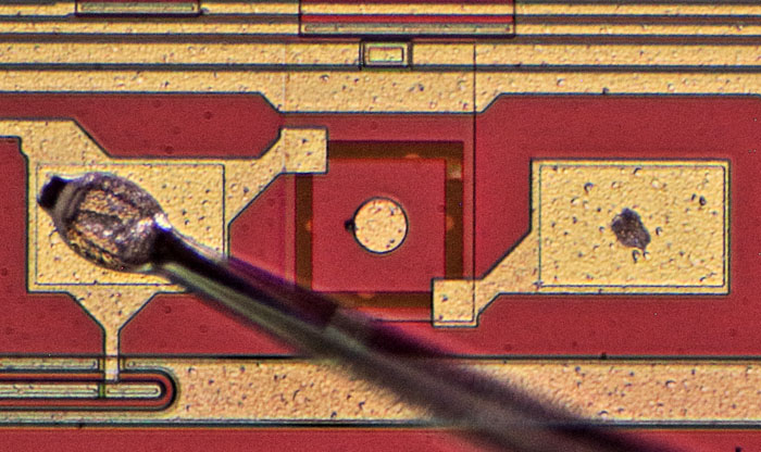
Like in most laser tuned circuits there is an additional bondpad with an tuneable rectangle to tune the tuning system.
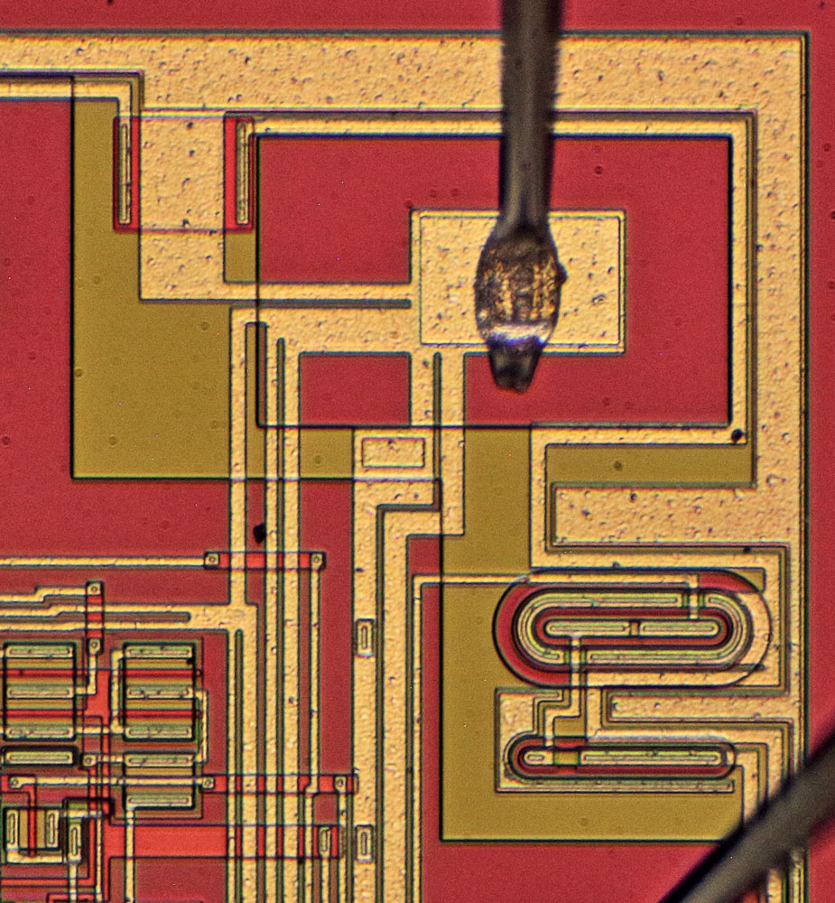
Some potentials (here Vee) are distributed with a lot of tracks that contain different star points.
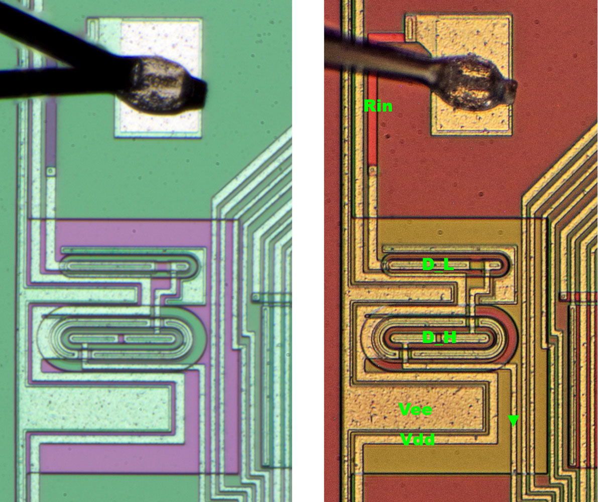
Here you can see the input protection, a series resistor followed by two diodes. Interesting detail: The metal line contacting the diodes is interrupted probably to force the current through the silicon and getting better overvoltage protection.
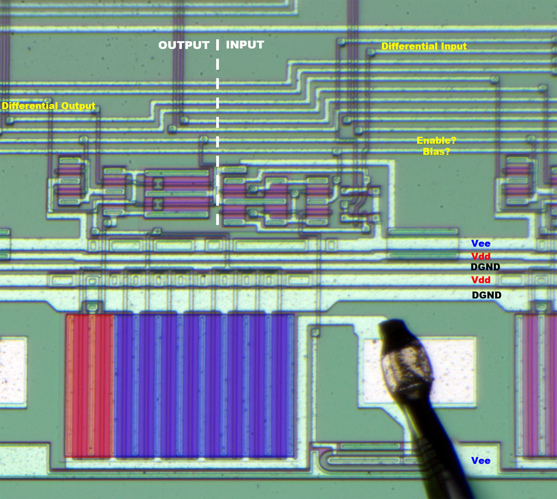
The output stages are easy to spot. They contain a small highside transistor (red) and a big lowside transistor. It seems there is an enable signal and a differential signal controlling the output.
Surprise: There is also an input stage with a differential output and a bias adjusting the threshold.
The output stages are supplied with exclusive Vdd and DGND lines.
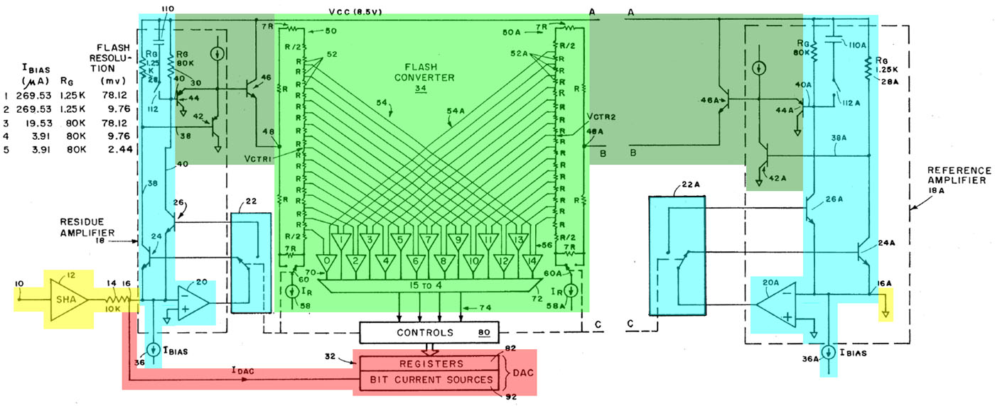
The datasheet refers to some patents. One of them is the US4804960 that contains an interesting schematic. Most of the circuit is symmetrical.
Yellow: On the left side there is the S&H circuit and a 10k resistor that converts the voltage into a current.
Red: The DAC sinks a current out of the summing node to compensate the input current as good as possible.
Cyan: The residual current is amplified with different amplification factors. The opamp 20 and the transistor 24 (or 26) do the amplification. The current sink 36 sets a bias current.
Dark green: Between the amplifier and the FADC there is a buffer stage.
Green: The FADC is built with 15 comparators and two resistor strings. The current sink 58 determines the resolution of the FDAC. The buffer transistor 46 lifts and sinks the complete resistor string. On the right side there is the same circuit supplying the comparators with the reference potential. This criss-cross arrangement compensates a lot of errors and drift effects. The LSBs are generated in the middle of the resistor strings.
The FADC has to measure smaller voltages each cycle.
In the second cycle the current sink 58 is switched by the switch 60. The current in the resistor string is divided by 8 and the resolution is eight times higher.
In the third cycle switch 60 is switched back and the amplifier is switched to transistor 26. The higher collector resistor gives us a amplification of 64.
In the fourth cycle the switch 60 is switched into the higher resolution again. Additionally switch 110 is closed to reduce the bandwidth from 6MHz to 800kHz. The conversion speed is reduced but also the noise is reduced.
In the fifth cycle the current through the resistor string is reduced further by a factor of 4.
The bias current 36 is adjusted too.
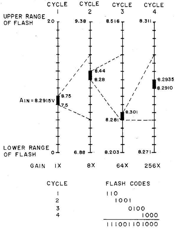
The patent shows one conversion. The FADC gives us a 4Bit value of the input voltage. The first three Bits of the DAC are configured with this value reducing the current in the summing node. In the next cycle the FADC gives us the next 4Bit and so on... In the last cycle (not shown here) the FADC adds the last 2Bit to the 12Bit value generated in the former cycles.
The Bits generated by the FADC are summed up to get the 12Bit value of the input signal. The FADC generates 4Bit but only 3Bit add up to the result. The fourth bit is for error correction. It can switch the LSB of the former 4Bit. That´s not a digital correction. Some of the current sinks in the DAC are doubled up.
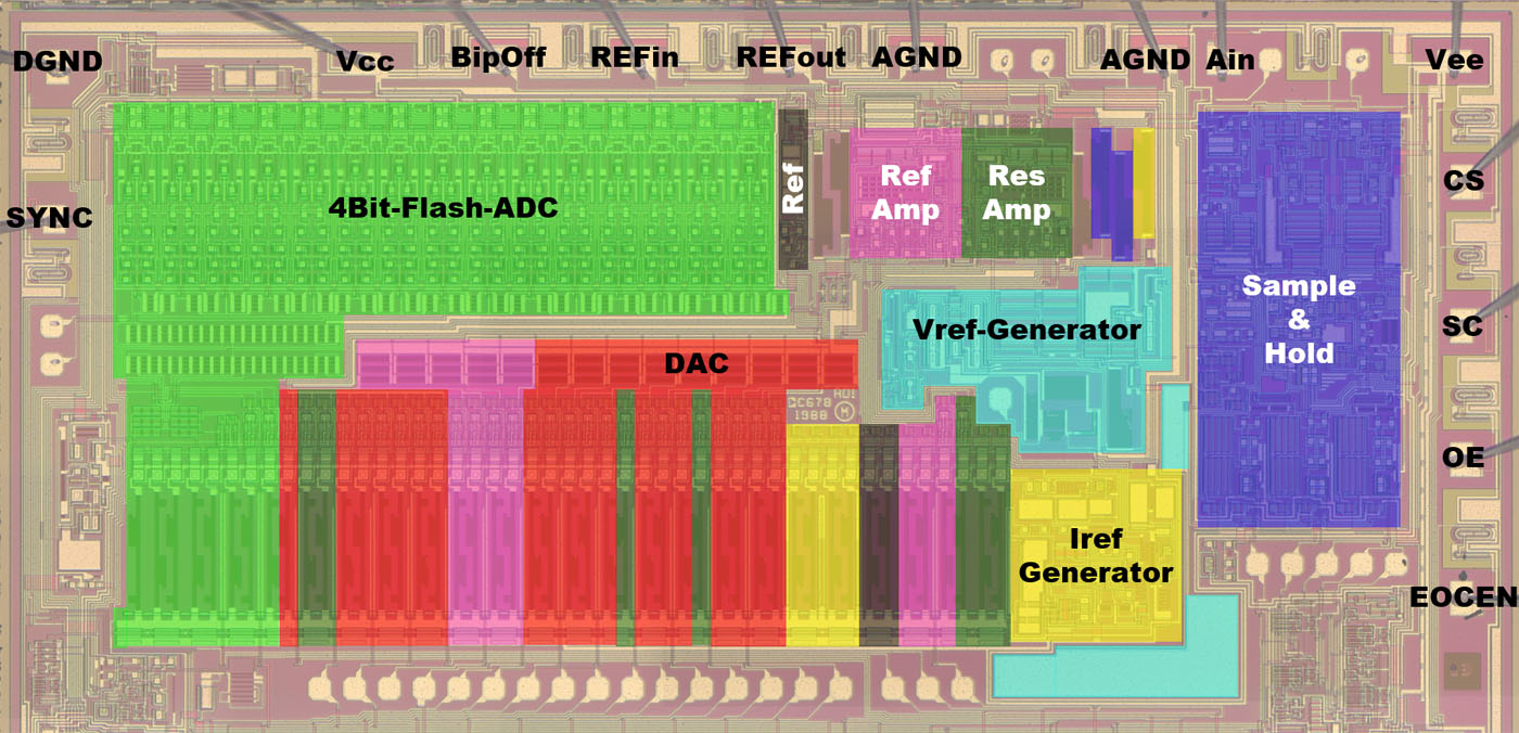
In the analog part of the die the Sample&Hold stage is on the right side (blue). A differential signal is fed to two resistors right of the residual voltage amplifier (dark green). Left of the amplifier is the reference amplifier (pink). Under the amplifiers there is the voltage reference (cyan) and the reference current generator (yellow). There is a active regulated reference potential on the die (black). The red area is the DAC. The FADC (green) consumes a lot of area although it converts just 4Bit.
Next part coming soon!


