Before I designed the 5 Transistor ESR meter, I designed and built an ESR meter using a digital panel meter.
The design is unusual in that it uses 10kHz, instead of the more usual 100kHz. By using a synchronous rectifier to measure the in-phase component of the capacitor impedance.
Jay_Diddy_B, thanks, that looks interesting.
Now, as usual, incoming bombardments of noob questions  :
:
- What is so special about that "synchronous rectifier" method compared to others common "cheap DIY" ESR measurement techniques ?
- Why 10 KHz ? How about other frequency like 100 KHz ? or lower ?
- Any pre-adjustments or tunings required when finished building it ?
This screen shot from the scope will help answer the questions.
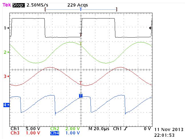
The upper trace is the output of the 10kHz oscillator.
The second trace is the output of the 10kHz bandpass filter, a reasonably nice sine wave.
The next trace is the output of the differential amplifier, that is the voltage across the capacitor under test.
The lower trace is the output of the synchronous detector. The imaginary components cancel. The in phase component, the resistive part is averaged and then displayed on the meter.
In this scope shot I am measuring a 4.7uF capacitor with an ESR of 1.2 Ohms. impedance Z= 1.2 -3.3j ohms, |Z|= 3.5 ohms.
The ESR meter correctly reads 1.2 Ohms.
10KHz was chosen as a compromise. 100kHz is the traditional frequency used for ESR measurements. At a 100KHz I would have needed some faster op-amps and a better analog switch.
I have checked this circuit against an HP 4274A LCR (Z) meter and it gives very accurate results for the cost.
There are several weaknesses in this design:
1) The amplitude of the square wave is dependant on how close the op-amp can swing to the rail.
2) The amplitude of the sine wave depends on being in the center of the band pass filter.
3) I tweaked the value of the R23 to obtain the calibration.
This circuit has a nice linear response. It is a true ESR meter, it is not an impedance meter. It use as nice low voltage test signal to allow in circuit measurements. It will work with a DMM, but you have to multiply the voltage read by 10x to get ohms.
Jay_Diddy_B


